Infiniti G37 Coupe. Manual - part 96
AV
DIAGNOSIS SYSTEM (AV CONTROL UNIT)
AV-137
< FUNCTION DIAGNOSIS >
[BOSE AUDIO WITHOUT NAVIGATION]
C
D
E
F
G
H
I
J
K
L
M
B
A
O
P
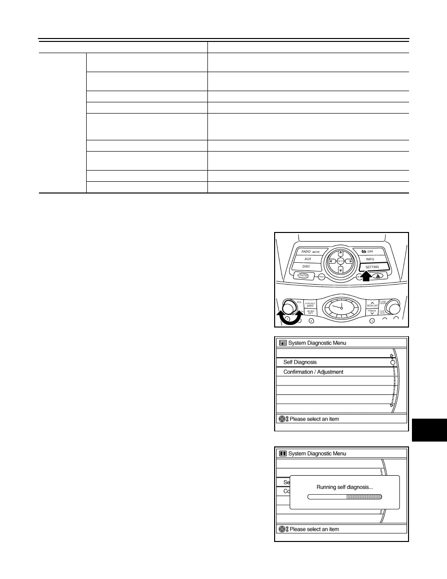
STARTING PROCEDURE
1.
Start the engine.
2.
Turn the audio system OFF.
3.
While pressing the “SETTING” button, turn the volume control
dial clockwise or counterclockwise for 40 clicks or more. (When
the self-diagnosis mode is started, a short beep will be heard.)
• Shifting from current screen to previous screen is performed
by pressing “BACK” button.
4.
The trouble diagnosis initial screen is displayed, and then the
items of “Self Diagnosis” and “Confirmation/Adjustment” can be
selected.
SELF-DIAGNOSIS MODE
1.
Start the self-diagnosis function and select “Self-diagnosis”.
-
Self-diagnosis subdivision screen is displayed, and the self-
diagnosis mode starts.
-
The bar graph visible on the center of the self-diagnosis subdivi-
sion screen indicates progress of the trouble diagnosis.
Confirmation/
Adjustment
Display Diagnosis
The confirmations of the tint with the color spectrum bar display and
shading of color with the gradation bar display can be performed.
Vehicle Signals
Diagnosis of signals can be performed for vehicle speed, parking brake,
lights, ignition switch, and reverse.
Speaker Test
The connection of a speaker can be confirmed by test tone.
Climate Control
Start auto air conditioner system self-diagnosis.
Error History
The system malfunction and the frequency when occurring in the past
are displayed. When the malfunctioning item is selected, the time and
place that the selected malfunction last occurred are displayed.
Vehicle CAN Diagnosis
The transmitting/receiving of CAN communication can be monitored.
AV COMM Diagnosis
The communication condition of each unit of Multi AV system can be
monitored.
Delete Unit Connection Log
Erase the connection history of unit and error history
Initialize Settings
Initializes the AV control unit memory.
Mode
Description
JSNIA0137GB
JSNIA0138GB
JSNIA0139GB