Infiniti G37 Coupe. Manual - part 87
AV
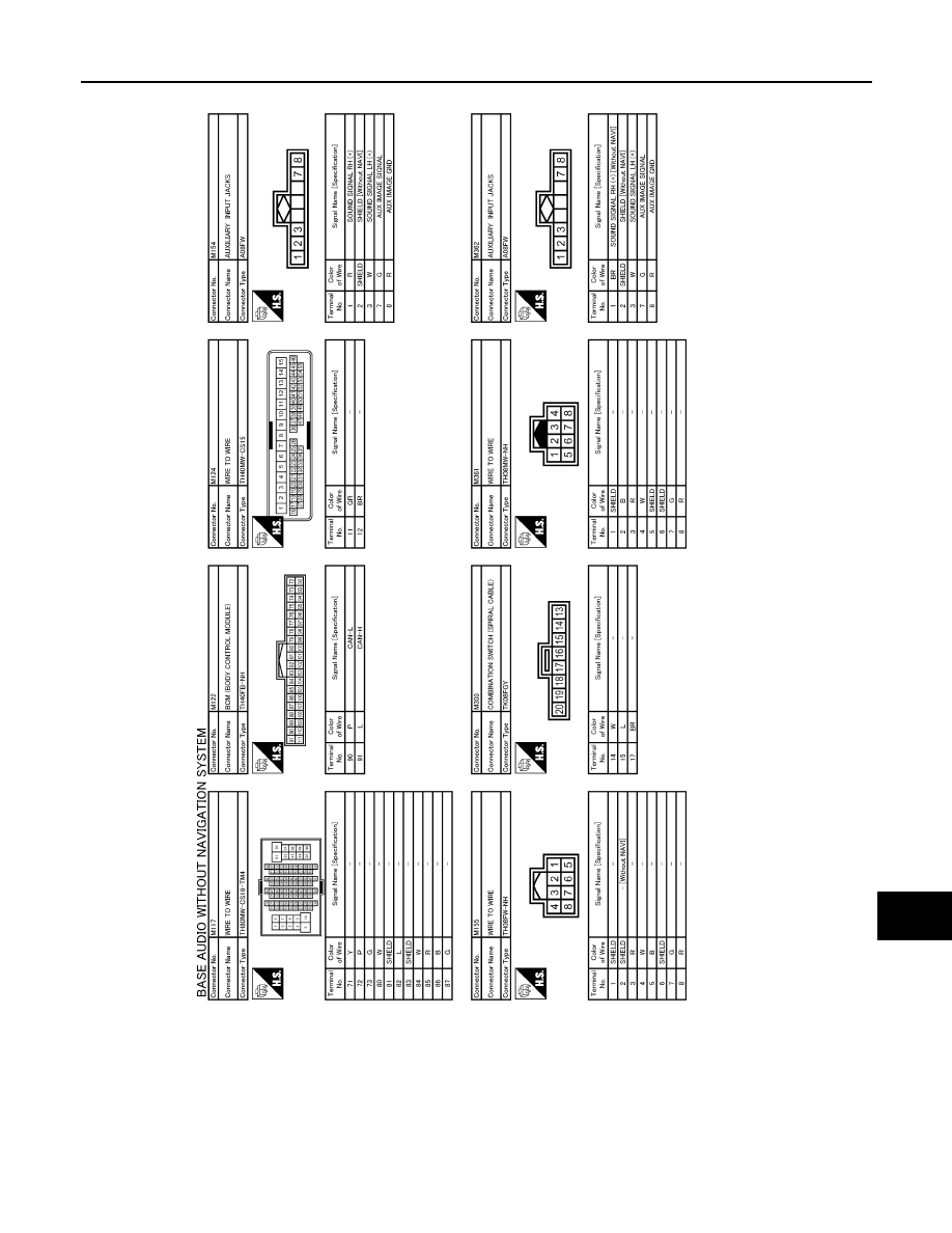
SATELLITE RADIO TUNER
AV-101
< ECU DIAGNOSIS >
[BASE AUDIO WITHOUT NAVIGATION]
C
D
E
F
G
H
I
J
K
L
M
B
A
O
P
JCNWA0460GB
|
|
|
AV SATELLITE RADIO TUNER AV-101 < ECU DIAGNOSIS > [BASE AUDIO WITHOUT NAVIGATION] C D E F G H I J K L M B A O P JCNWA0460GB |