Infiniti G37 Coupe. Manual - part 77


  Index      Infiniti     Infiniti G37 Coupe - service repair manual 2008 year


Search            


Content   ..  75  76  77  78   ..


Infiniti G37 Coupe. Manual - part 77


AV

AV CONTROL UNIT

AV-61

< ECU DIAGNOSIS >

[BASE AUDIO WITHOUT NAVIGATION]

C

D

E

F

G

H

I

J

K

L

M

B

A

O

P

6

(G)

15

(B)

Steering switch signal A

Input

Ignition 

switch 

ON

Keep pressing SOURCE 
switch.

 0 V

Keep pressing 

 switch.

0.7 V

Keep pressing 

 switch.

1.3 V

Except for above.

3.3 V

7

(V)

Ground

ACC power supply

Input

Ignition 

switch 

ACC

Battery voltage

8

(B)

Ground

GND

Ignition 

switch 

ON

0  V

9

(L)

Ground

Illumination signal

Input

OFF

Lighting switch is OFF.

0 V

Lighting switch is ON.

12 V

11

(BR)

12

(R)

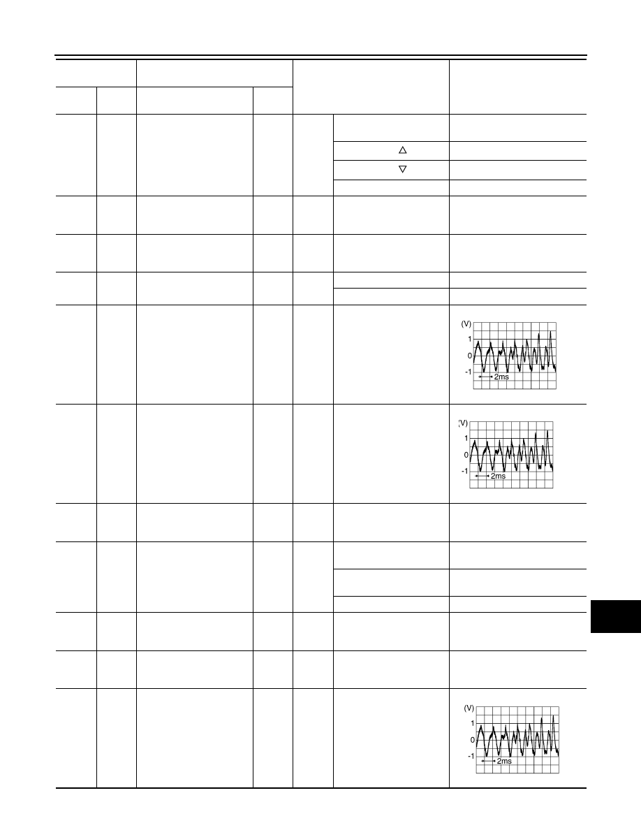
Sound signal door speaker 
RH

Output

Ignition 

switch 

ON

Voice output

13

(L)

14

(P)

Sound signal rear speaker 
RH

Output

Ignition 

switch 

ON

Voice output

15

(B)

Ground

Steering switch signal GND

Ignition 

switch 

ON

0  V

16

(L)

15

(B)

Steering switch signal B

Input

Ignition 

switch 

ON

Keep pressing VOL DOWN 
switch.

0 V

Keep pressing VOL UP 
switch.

0.7 V

Except for above.

3.3 V

19

(Y)

Ground

Battery power supply

Input

Ignition 

switch 

OFF

Battery voltage

20

(B)

Ground

GND

Ignition 

switch 

ON

0  V

22

(R)

21

(W)

Satellite radio sound signal 
LH

Input

Ignition 

switch 

ON

When satellite radio mode 
is selected

Terminal

(Wire color)

Description

Condition

Reference value

(Approx.)

+

Signal name

Input/

Output

SKIB3609E

SKIB3609E

SKIB3609E

AV-62

< ECU DIAGNOSIS >

[BASE AUDIO WITHOUT NAVIGATION]

AV CONTROL UNIT

24

(B)

23

(G)

Satellite radio sound signal 
RH

Input

Ignition 

switch 

ON

When satellite radio mode 
is selected

25

Shield

26

Shield

28

(W)

Ground

Request signal 
(SAT

CONT)

Input

Ignition 

switch 

ON

When satellite radio mode 
is selected

29

(B)

Ground

Communication signal 
(SAT

CONT)

Input

Ignition 

switch 

ON

When satellite radio mode 
is selected

30

(R)

Ground

Communication signal
(CONT

SAT)

Output

Ignition 

switch 

ON

When satellite radio mode 
is selected

33

FM sub

Input

34

AM–FM main

Input

35

Ground

Antenna amp. ON signal

Output

Ignition 

switch 

ACC

12  V

36

(R)

Ground

AUX image signal

Output

Ignition 

switch 

ON

At AUX image is displayed

37

(L)

Ground

AUX image GND

Ignition 

switch 

ON

0  V

Terminal

(Wire color)

Description

Condition

Reference value

(Approx.)

+

Signal name

Input/

Output

SKIB3609E

SKIA9299J

SKIA9300J

SKIA9301J

SKIB2251J

AV

AV CONTROL UNIT

AV-63

< ECU DIAGNOSIS >

[BASE AUDIO WITHOUT NAVIGATION]

C

D

E

F

G

H

I

J

K

L

M

B

A

O

P

38

(P)

Ground

RGB signal (B: blue)

Output

Ignition 

switch 

ON

Start confirmation/adjust-
ment mode, and then dis-
play color bar by selecting 
“Color Spectrum Bar” on 
DISPLAY DIAGNOSIS 
screen.

39

(L)

Ground

RGB signal (G: green)

Output

Ignition 

switch 

ON

Start confirmation/adjust-
ment mode, and then dis-
play color bar by selecting 
“Color Spectrum Bar” on 
DISPLAY DIAGNOSIS 
screen.

40

(G)

Ground

RGB signal (R: red)

Output

Ignition 

switch 

ON

Start confirmation/adjust-
ment mode, and then dis-
play color bar by selecting 
“Color Spectrum Bar” on 
DISPLAY DIAGNOSIS 
screen.

41

(Y)

Ground

RGB synchronizing signal

Output

Ignition 

switch 

ON

42

Shield

43

(P)

Ground

RGB area (YS) signal

Output

Ignition 

switch 

ON

At RGB image is displayed

5 V

At AUX image is displayed

44

(G)

Ground

Communication signal
(DISP

CONT)

Input

Ignition 

switch 

ON

When adjusting display-
brightness.

Terminal

(Wire color)

Description

Condition

Reference value

(Approx.)

+

Signal name

Input/

Output

SKIB2237J

SKIB2236J

SKIB2238J

SKIB3603E

PKIB4948J

PKIB5039J

AV-64

< ECU DIAGNOSIS >

[BASE AUDIO WITHOUT NAVIGATION]

AV CONTROL UNIT

45

(LG)

Ground

Horizontal synchronizing 
(HP) signal

Input

Ignition 

switch 

ON

46

(LG)

Ground

Signal GND

Ignition 

switch 

ON

0  V

47

(O)

Ground

Signal VCC

Output

Ignition 

switch 

ACC

9  V

49

Shield

50

Shield

55

Shield

56

(L)

Ground

Communication signal
(CONT

DISP)

Output

Ignition 

switch 

ON

When adjusting display-
brightness.

57

(GR)

Ground

Vertical synchronizing (VP) 
signal

Input

Ignition 

switch 

ON

58

(BR)

Ground

Inverter GND

Ignition 

switch 

ON

0  V

59

(Y)

Ground

Inverter VCC

Output

Ignition 

switch 

ACC

9  V

66

(R)

Ground

AUX image signal

Input

Ignition 

switch 

ON

When AUX mode is select-
ed

73

Shield

74

(L)

Ground

AUX image signal GND

Ignition 

switch 

ON

0  V

Terminal

(Wire color)

Description

Condition

Reference value

(Approx.)

+

Signal name

Input/

Output

SKIB3601E

PKIB5039J

SKIB3598E

SKIB2251J


Content   ..  75  76  77  78   ..