Infiniti G37 Coupe. Manual - part 73


  Index      Infiniti     Infiniti G37 Coupe - service repair manual 2008 year


Search            


Content   ..  71  72  73  74   ..


Infiniti G37 Coupe. Manual - part 73


AV

RGB SYNCHRONIZING SIGNAL CIRCUIT

AV-45

< COMPONENT DIAGNOSIS >

[BASE AUDIO WITHOUT NAVIGATION]

C

D

E

F

G

H

I

J

K

L

M

B

A

O

P

RGB SYNCHRONIZING SIGNAL CIRCUIT

Description

INFOID:0000000001689667

Transmit the RGB synchronizing signal to the display unit so as to synchronize the RGB image displayed with
AV control unit.

Diagnosis Procedure

INFOID:0000000001689669

1.

CHECK CONTINUITY RGB SYNCHRONIZING SIGNAL CIRCUIT

1.

Turn ignition switch OFF.

2.

Disconnect display unit connector and AV control unit connector.

3.

Check continuity between display unit harness connector terminal 19 and AV control unit harness connec-
tor terminal 41.

4.

Check continuity between display unit harness connector terminal 19 and ground.

Is the inspection result normal?

YES

>> GO TO 2.

NO

>> Repair harness or connector.

2.

CHECK RGB SYNCHRONIZING SIGNAL

1.

Connect display unit connector and AV control unit connector.

2.

Turn ignition switch ON.

3.

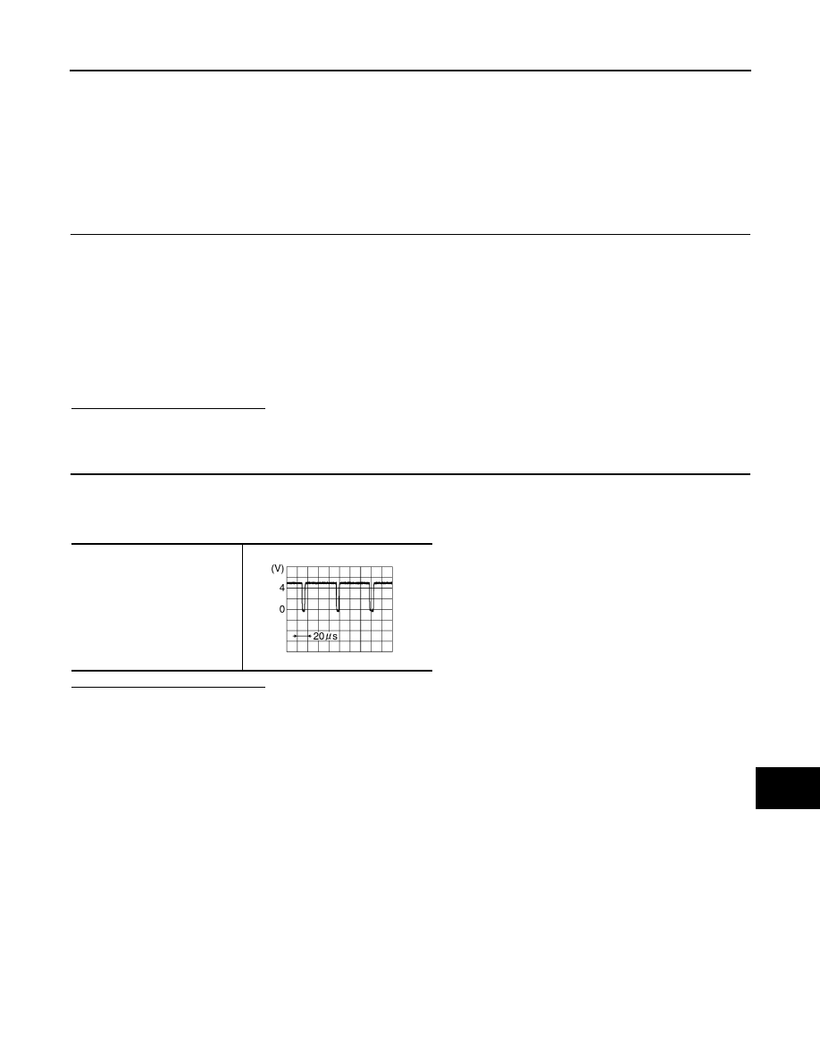
Check signal between display unit harness connector terminal 19 and ground.

Is the inspection result normal?

YES

>> Replace display unit.

NO

>> Replace AV control unit.

19 - 41

: Continuity should exist.

19 - Ground

: Continuity should not exist.

19 - Ground

SKIB3603E

AV-46

< COMPONENT DIAGNOSIS >

[BASE AUDIO WITHOUT NAVIGATION]

RGB AREA (YS) SIGNAL CIRCUIT

RGB AREA (YS) SIGNAL CIRCUIT

Description

INFOID:0000000001689672

Transmits the display area of RGB image displayed by AV control unit with RGB area (YS) signal to display
unit.

Diagnosis Procedure

INFOID:0000000001689671

1.

CHECK CONTINUITY RGB AREA (YS) SIGNAL CIRCUIT

1.

Turn ignition switch OFF.

2.

Disconnect display unit connector and AV control unit connector.

3.

Check continuity between display unit harness connector terminal 9 and AV control unit harness connec-
tor terminal 43.

4.

Check continuity between display unit harness connector terminal 9 and ground.

Is the inspection result normal?

YES

>> GO TO 2.

NO

>> Repair harness or connector.

2.

CHECK RGB AREA (YS) SIGNAL

1.

Connect display unit connector and AV control unit connector.

2.

Turn ignition switch ON.

3.

Check signal between display unit harness connector terminal 9 and ground.

Is the inspection result normal?

YES

>> Replace display unit.

NO

>> Replace AV control unit.

9 - 43

: Continuity should exist.

9 - Ground

: Continuity should not exist.

Terminal

Condition

Reference value

9 - Ground

Ignition 

switch 

ON

At RGB image is displayed

: Approx. 5 V

At AUX image is displayed

PKIB4948J

AV

HORIZONTAL SYNCHRONIZING (HP) SIGNAL CIRCUIT

AV-47

< COMPONENT DIAGNOSIS >

[BASE AUDIO WITHOUT NAVIGATION]

C

D

E

F

G

H

I

J

K

L

M

B

A

O

P

HORIZONTAL SYNCHRONIZING (HP) SIGNAL CIRCUIT

Description

INFOID:0000000001689673

In composite image (AUX image, camera image), transmit the vertical synchronizing (VP) signal and horizon-
tal synchronizing (HP) signal from display unit to AV control unit so as to synchronize the RGB images dis-
played with AV control unit such as the image quality adjusting menu, etc.

Diagnosis Procedure

INFOID:0000000001689674

1.

CHECK CONTINUITY HORIZONTAL SYNCHRONIZING (HP) SIGNAL CIRCUIT

1.

Turn ignition switch OFF.

2.

Disconnect display unit connector and AV control unit connector.

3.

Check continuity between display unit harness connector terminal 8 and AV control unit harness connec-
tor terminal 45.

4.

Check continuity between display unit harness connector terminal 8 and ground.

Is the inspection result normal?

YES

>> GO TO 2.

NO

>> Repair harness or connector.

2.

CHECK HORIZONTAL SYNCHRONIZING (HP) SIGNAL

1.

Connect display unit connector and AV control unit connector.

2.

Turn ignition switch ON.

3.

Check signal between display unit harness connector terminal 8 and ground.

Is the inspection result normal?

YES

>> Replace AV control unit.

NO

>> Replace display unit.

8 - 45

: Continuity should exist.

8 - Ground

: Continuity should not exist.

8 - Ground

SKIB3601E

AV-48

< COMPONENT DIAGNOSIS >

[BASE AUDIO WITHOUT NAVIGATION]

VERTICAL SYNCHRONIZING (VP) SIGNAL CIRCUIT

VERTICAL SYNCHRONIZING (VP) SIGNAL CIRCUIT

Description

INFOID:0000000001689675

In composite image (AUX image, camera image), transmit the vertical synchronizing (VP) signal and horizon-
tal synchronizing (HP) signal from display unit to AV control unit so as to synchronize the RGB images dis-
played with AV control unit such as the image quality adjusting menu, etc.

Diagnosis Procedure

INFOID:0000000001689676

1.

CHECK CONTINUITY VERTICAL SYNCHRONIZING (VP) SIGNAL CIRCUIT

1.

Turn ignition switch OFF.

2.

Disconnect display unit connector and AV control unit connector.

3.

Check continuity between display unit harness connector terminal 20 and AV control unit harness connec-
tor terminal 57.

4.

Check continuity between display unit harness connector terminal 20 and ground.

Is the inspection result normal?

YES

>> GO TO 2.

NO

>> Repair harness or connector.

2.

CHECK VERTICAL SYNCHRONIZING (VP) SIGNAL

1.

Connect display unit connector and AV control unit connector.

2.

Turn ignition switch ON.

3.

Check signal between display unit harness connector terminal 20 and ground.

Is the inspection result normal?

YES

>> Replace AV control unit.

NO

>> Replace display unit.

20 - 57

: Continuity should exist.

20 - Ground

: Continuity should not exist.

20 - Ground

SKIB3598E


Content   ..  71  72  73  74   ..