Infiniti G37 Coupe. Manual - part 68


  Index      Infiniti     Infiniti G37 Coupe - service repair manual 2008 year


Search            


Content   ..  66  67  68  69   ..


Infiniti G37 Coupe. Manual - part 68


AV

DIAGNOSIS SYSTEM (AV CONTROL UNIT)

AV-25

< FUNCTION DIAGNOSIS >

[BASE AUDIO WITHOUT NAVIGATION]

C

D

E

F

G

H

I

J

K

L

M

B

A

O

P

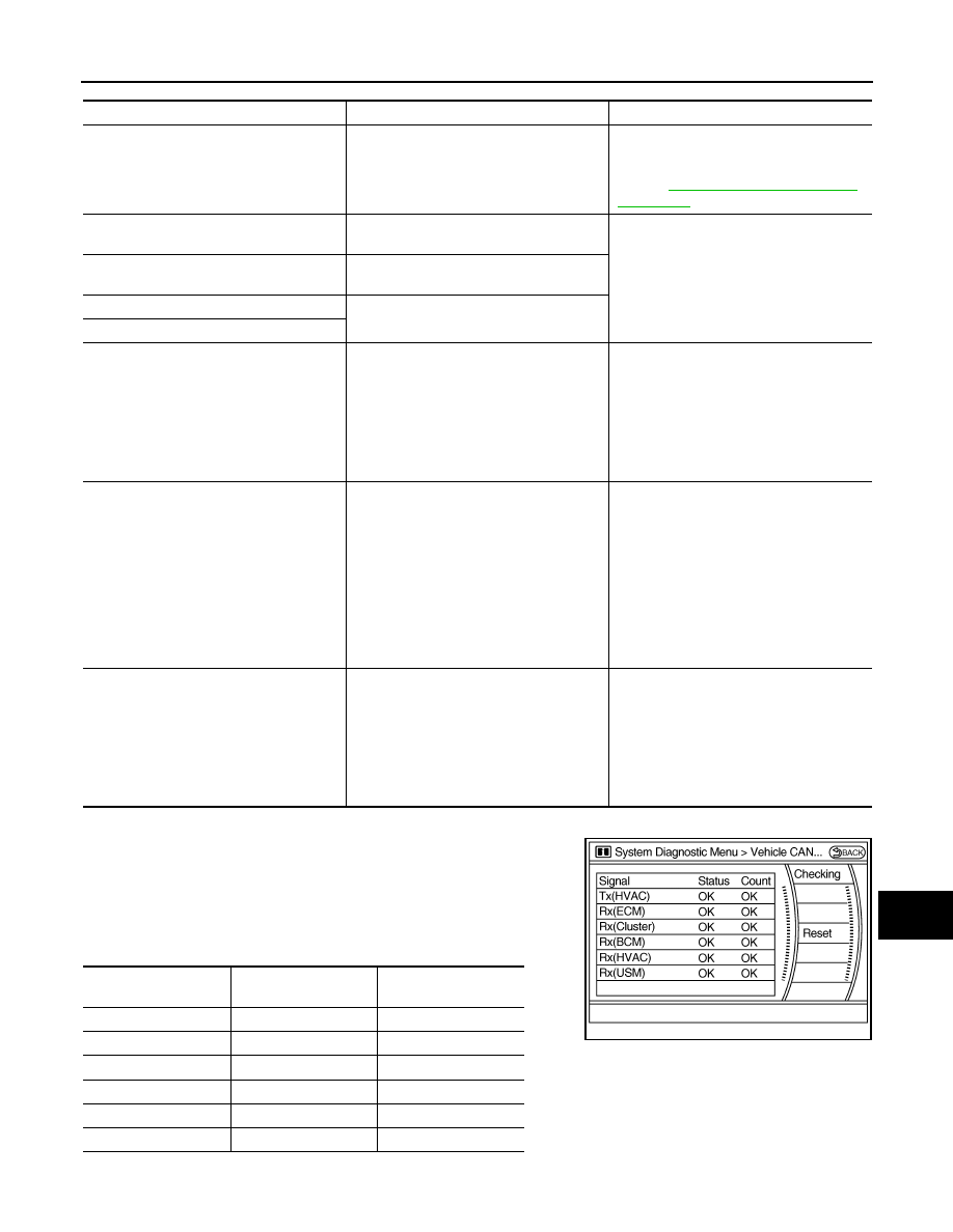
Vehicle CAN Diagnosis

• CAN communication status and error counter is displayed.
• The error counter displays “OK” if any malfunction was not

detected in the past and displays “0” if a malfunction is detected. It
increases by 1 if the condition is normal at the next ignition switch
ON cycle. The upper limit of the counter is 39.

• The error counter is erased if reset.

AV COMM Diagnosis

Error item

Description

Possible malfunction factor/Action to take

CAN COMM CIRCUIT

CAN communication malfunction is detect-
ed.

Perform diagnosis with CONSULT-III, and 
then repair the malfunctioning parts accord-
ing to the diagnosis results.
Refer to 

AV-26, "CONSULT - III Function 

(MULTI AV)"

.

CONTROL UNIT (CAN)

CAN initial diagnosis malfunction is detect-
ed.

Replace the AV control unit.

CONTROL UNIT (AV)

AV communication circuit initial diagnosis 
malfunction is detected.

FLASH-ROM Error Of Control Unit

AV control unit malfunction is detected.

CAN Controller Memory Error

Front Display Connection Error

• Display unit power supply and ground 

circuit malfunction is detected.

• Malfunction is detected in communica-

tion circuit between AV control unit and 
display unit.

• Malfunction is detected in communica-

tion signal between AV control unit and 
display unit.

• Display unit power supply and ground 

circuit.

• Communication circuit between AV con-

trol unit and display unit.

SAT Connection Error

• Satellite radio tuner power supply and 

ground circuit malfunction is detected.

• Malfunction is detected in communica-

tion circuit between AV control unit and 
satellite radio tuner.

• Malfunction is detected in communica-

tion signal between AV control unit and 
satellite radio tuner.

• Malfunction is detected in request signal 

circuit between AV control unit and satel-
lite radio tuner.

• Satellite radio tuner power supply and 

ground circuit.

• Communication circuit between AV con-

trol unit and satellite radio tuner.

• Request signal circuit between AV con-

trol unit and satellite radio tuner.

• AV COMM CIRCUIT
• Switches Connection Error

• Multifunction switch power supply and 

ground circuit malfunction is detected.

• Malfunction is detected in AV communi-

cation circuit between AV control unit and 
multifunction switch.

• Malfunction is detected in AV communi-

cation signal between AV control unit and 
multifunction switch.

• Multifunction switch power supply and 

ground circuits.

• AV communication circuit between AV 

control unit and multifunction switch.

Items

Display (Current)

Malfunction counter

(Past)

Tx (HVAC)

OK / UNKWN

OK / 0 – 39

Rx (ECM)

OK / UNKWN

OK / 0 – 39

Rx (Cluster)

OK / UNKWN

OK / 0 – 39

Rx (BCM)

OK / UNKWN

OK / 0 – 39

Rx (HVAC)

OK / UNKWN

OK / 0 – 39

Rx (USM)

OK / UNKWN

OK / 0 – 39

JSNIA0080GB

AV-26

< FUNCTION DIAGNOSIS >

[BASE AUDIO WITHOUT NAVIGATION]

DIAGNOSIS SYSTEM (AV CONTROL UNIT)

• Displays the communication status between AV control unit (mas-

ter unit) and each unit.

• The error counter displays “OK” if any malfunction was not

detected in the past and displays “0” if a malfunction is detected. It
increases by 1 if the condition is normal at the next ignition switch
ON cycle. The upper limit of the counter is 39.

• If it resets, the error counter is erased.

Delete Unit Connection Log

Deletes any unit connection records and error records from the AV
control unit memory. (Clear the records of the unit that has been
removed)

Initialize Settings

Initializes the AV control unit memory.

CONSULT - III Function (MULTI AV)

INFOID:0000000001559126

CONSULT-III FUNCTIONS

CONSULT-III performs the following functions via the communication with the AV control unit.

AV COMMUNICATION

When “AV communication” of “CAN Diag Support Monitor” is selected, the following function will be performed.

Items

Status

(Current)

Counter

(Past)

C Tx (ITM–SW)

OK / UNKWN

OK / 0 - 39

C Rx (PrimarySW–ITM)

OK / UNKWN

OK / 0 - 39

C Rx (XM–ITM)

JSNIA0213GB

JSNIA0154GB

JSNIA0155GB

Diagnosis mode

Description

Ecu Identification

The part number of AV control unit can be checked.

Self Diagnostic Result

Performs a diagnosis on the AV control unit and a connection diagnosis for the communication 
circuit of the Multi AV system, and displays the current and past malfunctions collectively.

Data Monitor

The diagnosis of vehicle signal that is input to the AV control unit can be performed.

AV communication

AV&NAVI C/U

Displays the communication status from AV control unit to each unit as well as the error 
counter.

AUDIO

Displays the AV control unit communication status and the error counter.

AV

DIAGNOSIS SYSTEM (AV CONTROL UNIT)

AV-27

< FUNCTION DIAGNOSIS >

[BASE AUDIO WITHOUT NAVIGATION]

C

D

E

F

G

H

I

J

K

L

M

B

A

O

P

ECU IDENTIFICATION

The part number of AV control unit is displayed.

SELF DIAGNOSIS RESULT

• In CONSULT-III self-diagnosis, self-diagnosis results and error history are displayed collectively.
• The current malfunction indicates “CRNT”. The past malfunction indicates “PAST”.
• The timing is displayed as “0” if any of the error codes [U1000], [U1010], [U1300] and [U1310] is detected.

The counter increases by 1 if the condition is normal at the next ignition switch ON cycle.

Self-diagnosis detection range

Self-diagnosis results display item

JPNIA0515GB

Error item

Description

Possible malfunction factor/Action to take

CAN COMM CIRCUIT [U1000]

CAN communication malfunction is detect-
ed.

Perform diagnosis with CONSULT-III, and 
then repair the malfunctioning parts accord-
ing to the diagnosis results.
Refer to 

AV-26, "CONSULT - III Function 

(MULTI AV)"

.

CONTROL UNIT (CAN) [U1010]

CAN initial diagnosis malfunction is detect-
ed.

Replace the AV control unit.

CONTROL UNIT (AV) [U1310]

AV communication circuit initial diagnosis 
malfunction is detected.

Control Unit FLASH-ROM [U1200]

AV control unit malfunction is detected.

CAN CONT [U1216]

FRONT DISP CONN [U1243]

• Display unit power supply and ground 

circuit malfunction is detected.

• Malfunction is detected in communica-

tion circuit between AV control unit and 
display unit.

• Malfunction is detected in communica-

tion signal between AV control unit and 
display unit.

• Display unit power supply and ground 

circuit.

• Communication circuit between AV con-

trol unit and display unit.

AV-28

< FUNCTION DIAGNOSIS >

[BASE AUDIO WITHOUT NAVIGATION]

DIAGNOSIS SYSTEM (AV CONTROL UNIT)

DATA MONITOR

ALL SIGNALS

• Displays the status of the following vehicle signals inputted into the AV control unit.
• For each signal, actual signal can be compared with the condition recognized on the system.

SELECTION FROM MENU

Allows the technician to select which vehicle signals should be displayed and displays the status of the
selected vehicle signals.

SAT CONN [U1255]

• Satellite radio tuner power supply and 

ground circuit malfunction is detected.

• Malfunction is detected in communica-

tion circuit between AV control unit and 
satellite radio tuner.

• Malfunction is detected in communica-

tion signal between AV control unit and 
satellite radio tuner.

• Malfunction is detected in request signal 

circuit between AV control unit and satel-
lite radio tuner.

• Satellite radio tuner power supply and 

ground circuit.

• Communication circuit between AV con-

trol unit and satellite radio tuner.

• Request signal circuit between AV con-

trol unit and satellite radio tuner.

• AV COMM CIRCUIT [U1300]
• SWITCH CONN [U1240]

• Multifunction switch power supply and 

ground circuit malfunction is detected.

• Malfunction is detected in AV communi-

cation circuit between AV control unit and 
multifunction switch.

• Malfunction is detected in AV communi-

cation signal between AV control unit and 
multifunction switch.

• Multifunction switch power supply and 

ground circuits.

• AV communication circuit between AV 

control unit and multifunction switch.

Error item

Description

Possible malfunction factor/Action to take

Display Item

Dis-
play

Vehicle status

Remarks

VHCL SPD SIG

On

Vehicle speed >0 km/h (0 MPH)

Changes in indication may be delayed. This is nor-
mal.

Off

Vehicle speed =0 km/h (0 MPH)

PKB SIG

On

Parking brake is applied.

Off

Parking brake is released.

ILLUM SIG

On

Light switch ON

Off

Light switch OFF

IGN SIG

On

Ignition switch ON

Off

Ignition switch in ACC position

REV SIG

On

Shift the selector lever to “R” position

Changes in indication may be delayed. This is nor-
mal.

Off

Shift the selector lever other than “R” 
position

Item to be selected

Description

VHCL SPD SIG

The same as when “ALL SIGNALS” 
is selected.

PKB SIG

ILLUM SIG

IGN SIG

REV SIG


Content   ..  66  67  68  69   ..