Infiniti G37 Coupe. Manual - part 61
ADP-238
< ON-VEHICLE REPAIR >
SEAT MEMORY SWITCH
SEAT MEMORY SWITCH
Exploded View
INFOID:0000000001693808
Removal and Installation
INFOID:0000000001693809
REMOVAL
CAUTION:
When removing and installing, use shop cloths to protect parts from damage.
1.
Disconnect battery negative terminal.
2.
Remove front door finisher (1). Refer to
.
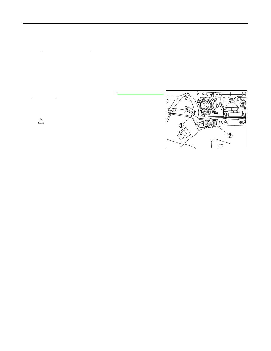
3.
Press pawls and remove seat memory switch (2) from front door
finisher (1).
INSTALLATION
Install in reverse order of removal.
CAUTION:
Be sure to clump the harness to the right place.
:
Pawl
JMJIA0197ZZ