Infiniti G37 Coupe. Manual - part 36


  Index      Infiniti     Infiniti G37 Coupe - service repair manual 2008 year


Search            


Content   ..  34  35  36  37   ..


Infiniti G37 Coupe. Manual - part 36


ADP-138

< COMPONENT DIAGNOSIS >

RECLINING RELAY

Is the inspection result normal?

YES

>> GO TO 4.

NO

>> Repair or replace harness or connector.

4.

CHECK DIODE 2

Refer to 

ADP-139, "BACKWARD : Component Inspection (Diode 2)"

.

Is the inspection result normal?

YES

>> GO TO 5.

NO

>> Replace diode 2.

5.

FORWARD SWITCH CIRCUIT

1.

Turn ignition switch OFF.

2.

Disconnect forward switch.

3.

Check continuity between forward switch harness connector and diode 2 harness connector.

4.

Check continuity between forward switch harness connector and ground.

Is the inspection result normal?

YES

>> GO TO 6.

NO

>> Repair or replace harness or connector.

6.

CHECK RECLINING RELAY (BACKWARD)

Refer to 

ADP-138, "BACKWARD : Component Inspection (Reclining Relay)"

.

Is the inspection result normal?

YES

>> GO TO 7.

NO

>> Replace reclining relay.

7.

CHECK INTERMITTENTE INCIDENT

Refer to 

GI-38, "Intermittent Incident"

.

>> INSPECTION END

BACKWARD : Component Inspection (Reclining Relay)

INFOID:0000000001754011
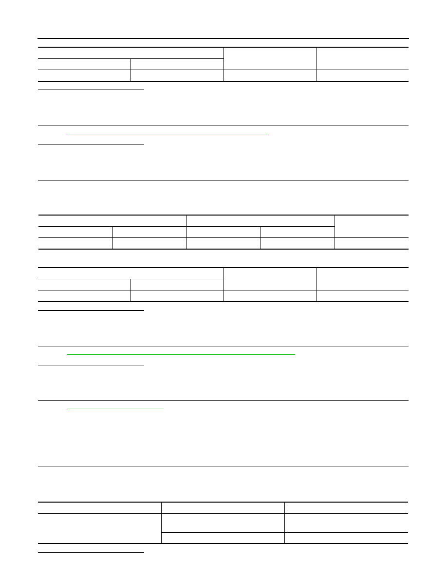
1.

CHECK RECLINING RELAY (BACKWARD)

1.

Turn ignition switch OFF.

2.

Remove reclining relay (backward).

3.

Check the continuity between reclining relay (backward) terminals under the following conditions.

Is the inspection result normal?

Reclining relay (backward)

Ground

Continuity

Connector

Terminal

B520

6

Ground

Not existed

Forward switch

Diode 2

Continuity

Connector

Terminal

Connector

Terminal

B512

41

B522

41

Existed

Forward switch

Ground

Continuity

Connector

Terminal

B512

41

Ground

Not existed

Terminals

Condition

Continuity

15 and 44

12 V direct current supply between termi-
nals 94 and 6

Not existed

No current supply

Existed

RECLINING RELAY

ADP-139

< COMPONENT DIAGNOSIS >

C

D

E

F

G

H

I

K

L

M

A

B

ADP

N

O

P

YES

>> INSPECTION END

NO

>> Replace reclining relay (backward).

BACKWARD : Component Inspection (Diode 2)

INFOID:0000000001754013

1.

CHECK DIODE 2

1.

Turn ignition switch OFF.

2.

Remove diode 2.

3.

Check the continuity between diode 2 terminals under the following conditions.

Is the inspection result normal?

YES

>> INSPECTION END

NO

>> Replace diode 2.

Terminals

Continuity

(+)

(–)

6

41

Existed

41

6

Not existed

ADP-140

< COMPONENT DIAGNOSIS >

SEAT MEMORY INDICATOR LAMP

SEAT MEMORY INDICATOR LAMP

Description

INFOID:0000000001693783

• Memory switch is equipped on the seat memory switch installed on the driver side door trim. The operation

signal is inputted to the automatic drive positioner control unit when the memory switch is operated.

• The status of automatic drive positioner system can be checked according to the illuminating/flashing status.

Component Function Check

INFOID:0000000001693784

1.

CHECK FUNCTION

1.

Select “MEMORY SW INDCTR” in “Active Test” mode with CONSULT-III. 

2.

Check the memory indicator operation.

Is the operation of relevant parts normal?

YES

>> INSPECTION END

NO

>> Perform diagnosis procedure. Refer to 

ADP-140, "Diagnosis Procedure"

.

Diagnosis Procedure

INFOID:0000000001693785

1.

CHECK MEMORY INDICATOR CIRCUIT

1.

Turn ignition switch OFF.

2.

Disconnect automatic drive positioner control unit connector and seat memory switch connector.

3.

Check continuity between automatic drive positioner control unit harness connector and seat memory
switch harness connector.

4.

Check continuity between automatic drive positioner control unit harness connector and ground.

Is the inspection result normal?

YES

>> GO TO 2.

NO

>> Repair or replace harness.

2.

CHECK MEMORY INDICATOR POWER SUPPLY

Check voltage between seat memory switch harness connector and ground.

Is the inspection result normal?

YES

>> GO TO 3.

NO

>>

Check the following.

• Fuse

Test item

Description

MEMORY SW INDCTR

OFF

Memory switch indicator

OFF

ON-1

Indicator 1: ON

ON-2

Indicator 2: ON

Automatic drive positioner

control unit connector

Terminal

Seat memory switch

connector

Terminal

Continuity

M51

12

D5

6

Existed

13

7

Automatic drive positioner

control unit connector

Terminal

Ground

Continuity 

M51

12

Not existed

13

Seat memory switch

connector

Terminals 

Voltage (V) 

(Approx.)

(+)

(–)

D5

5

Ground

Battery voltage

SEAT MEMORY INDICATOR LAMP

ADP-141

< COMPONENT DIAGNOSIS >

C

D

E

F

G

H

I

K

L

M

A

B

ADP

N

O

P

• Harness for open or short between memory indicator and fuse.

3.

CHECK MEMORY INDICATOR

Refer to 

ADP-141, "Component Inspection"

.

Is the inspection result normal?

YES

>> GO TO 4.

NO

>> Replace seat memory switch.

4.

CHECK INTERMITTENT INCIDENT

Refer to 

GI-38, "Intermittent Incident"

.

Is the inspection result normal?

YES

>> Replace automatic drive positioner control unit.

NO

>> Repair or replace the malfunctioning part.

Component Inspection

INFOID:0000000001693786

1.

CHECK SEAT MEMORY INDICATOR

1.

Disconnect seat memory switch connector.

2.

Check continuity between seat memory switch terminals.

Is the inspection result normal?

YES

>> INSPECTION END

NO

>> Replace seat memory switch.

Terminal

Continuity

Seat memory switch

(+)

(-)

5

6

Existed

7

6

5

Not exsisted

7


Content   ..  34  35  36  37   ..