Infiniti G37 Coupe. Manual - part 22
ADP-82
< COMPONENT DIAGNOSIS >
TILT SWITCH
Is the inspection result normal?
YES
>> GO TO 3.
NO
>> Repair or replace harness.
3.
CHECK AUTOMATIC DRIVE POSITIONER CONTROL UNIT OUTPUT
1.
Connect automatic drive positioner control unit connector.
2.
Turn ignition switch ON.
3.
Check voltage between automatic drive positioner control unit harness connector and ground.
Is the inspection result normal?
YES
>> GO TO 4.
NO
>> Replace automatic drive positioner control unit.
4.
CHECK TILT SWITCH
ADP-82, "Component Inspection"
.
Is the inspection result normal?
YES
>> GO TO 5.
NO
>> Replace tilt & telescopic switch.
5.
CHECK INTERMITTENT INCIDENT
GI-38, "Intermittent Incident"
Is the inspection result normal?
YES
>> Replace automatic drive positioner control unit.
NO
>> Repair or replace the malfunctioning part.
Component Inspection
INFOID:0000000001693701
1.
CHECK TILT SWITCH
1.
Turn ignition switch OFF.
2.
Disconnect tilt & telescopic switch connector.
3.
Check continuity between tilt & telescopic switch terminals.
Is the inspection result normal?
YES
>> INSPECTION END
NO
>> Replace tilt & telescopic switch.
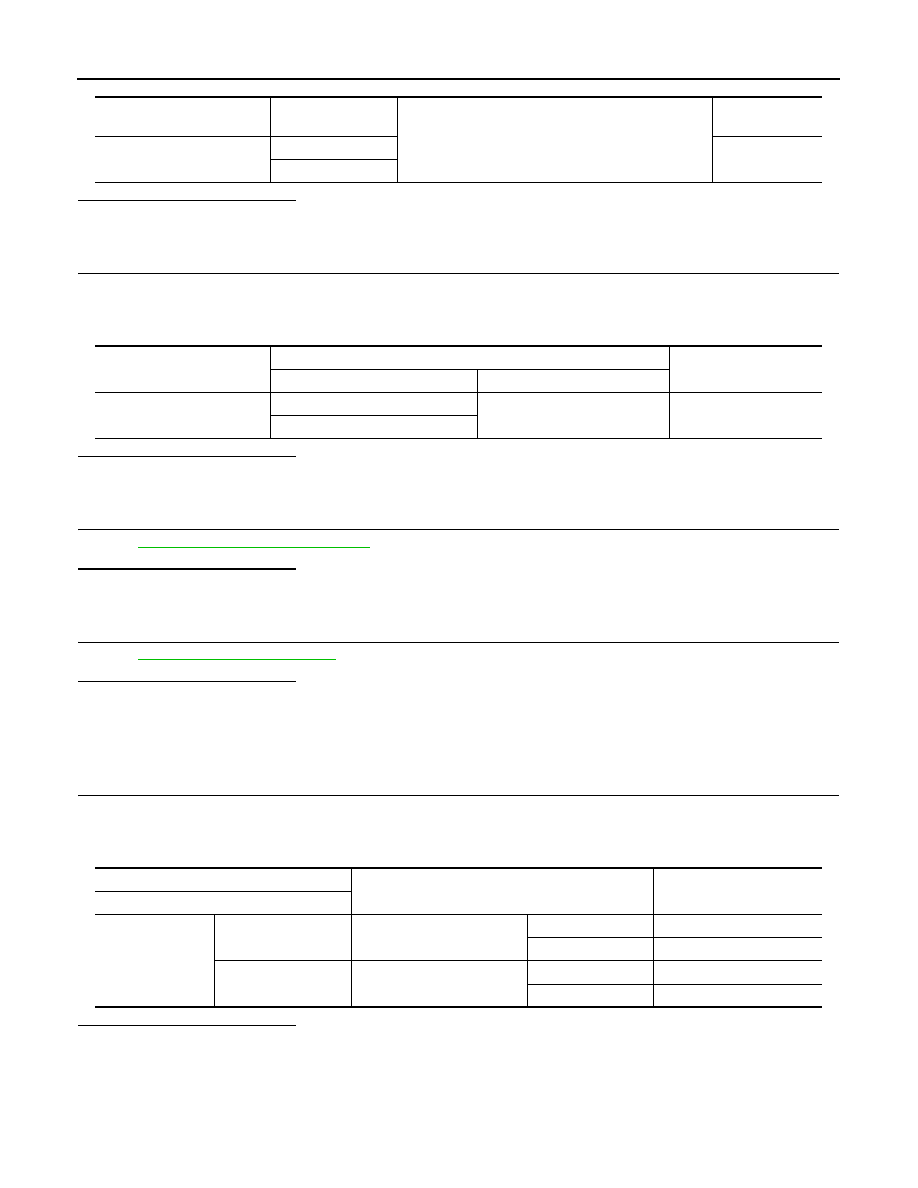
Automatic drive positioner
control unit connector
Terminal
Ground
Continuity
M51
1
Not existed
17
Automatic drive positioner
control unit connector
Terminals
Voltage (V)
(Approx.)
(+)
(–)
M51
1
Ground
Battery voltage
17
Terminal
Condition
Continuity
Tilt switch
1
4
Tilt switch (up)
Operate
Existed
Release
Not existed
5
Tilt switch (down)
Operate
Existed
Release
Not existed