Infiniti G37 Coupe. Manual - part 12


  Index      Infiniti     Infiniti G37 Coupe - service repair manual 2008 year


Search            


Content   ..  10  11  12  13   ..


Infiniti G37 Coupe. Manual - part 12


ADP-42

< FUNCTION DIAGNOSIS >

AUTOMATIC DRIVE POSITIONER SYSTEM

JMJIA0844ZZ

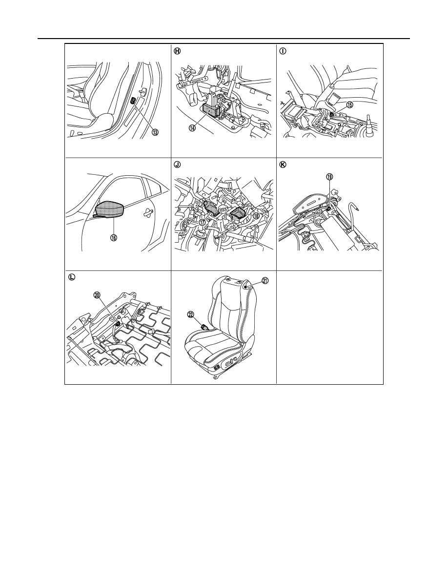
13. Driver side door switch B16

14. A/T device (detention switch) M137

15. Parking brake switch B14

16. Door mirror (driver side) D3

17. Telescopic motor M49

18. Tilt motor M49

19. Forward switch B512

20. Sliding limit switch B514

21. Power walk-in switch B513

22.

Seat belt buckle switch (driver side) 
B13

H.

View with center console assembly 
is removed.

I.

View with center console assembly 
is removed.

J.

View with instrument driver lower 
panel is removed.

K.

View with seat back pad is removed. L.

View with seat cushion pad is re-
moved.

AUTOMATIC DRIVE POSITIONER SYSTEM

ADP-43

< FUNCTION DIAGNOSIS >

C

D

E

F

G

H

I

K

L

M

A

B

ADP

N

O

P

POWER WALK-IN FUNCTION : Component Description

INFOID:0000000001838023

CONTROL UNITS

INPUT PARTS

Switches

Sensors

JMJIA0845ZZ

23. Reclining motor B523

24. Reclining relay (backward) B520

25. Reclining relay (forawrd) B519

26.

Reclining switch 
(Power seat switch B510)

27.

Sliding, lifting switch
(Power seat switch B510)

28. Sliding sensor B526

29. Lifting motor (front) B527

30. Sliding motor B525

31. Lifting motor (rear) B529

M.

View with seat cushion pad and seat-
back pad are removed.

N.

Backside of seat cushion

Item

Function

Driver seat control unit

• Main units of automatic drive positioner system
• It is connected to the CAN.
• It communicates with the automatic drive positioner control via UART communi-

cation.

BCM

Transmit the following status to the driver seat control unit via CAN communication.
• Driver door: OPEN/CLOSE
• Starter: CRANKING/OTHER

Unified meter and A/C amp.

Transmit the vehicle speed signal to the driver seat control unit via CAN communi-
cation.

Item

Function

Front door switch (driver side)

Detect front door (driver side) open/close status. 

Power walk-in switch

Perform the power walk-in operation by operating the power walk-in switch.

Sliding limit switch

Detect the front end position of seat sliding during the power walk-in function front-
ward operation.

Seat belt buckle switch

Detect the seat belt fastening/releasing condition.

Forward switch

Detect the folded up/folded down condition of seatback that is the operation condi-
tion of power walk-in function.

Item

Function

Sliding sensor

Detect the forward/backward position of seat.

ADP-44

< FUNCTION DIAGNOSIS >

AUTOMATIC DRIVE POSITIONER SYSTEM

OUTPUT PARTS

Item

Function

Sliding motor

Slide the seat forward/backward.

DIAGNOSIS SYSTEM (DRIVER SEAT C/U)

ADP-45

< FUNCTION DIAGNOSIS >

C

D

E

F

G

H

I

K

L

M

A

B

ADP

N

O

P

DIAGNOSIS SYSTEM (DRIVER SEAT C/U)

Diagnosis Description

INFOID:0000000001693647

The automatic drive positioner system can be checked and diagnosed for component operation with CON-
SULT-III. 

DIAGNOSTIC MODE

CONSULT-III Function

INFOID:0000000001693648

SELF DIAGNOSTIC RESULTS

Refer to 

ADP-160, "DTC Index"

.

DATA MONITOR

Diagnostic mode

Description

SELF-DIAG RESULTS

Performs self-diagnosis for the auto drive positioner system and displays the results.

DATA MONITOR

Displays input signals transmitted from various switches and sensors to driver seat con-
trol unit in real time.

CAN DIAG SUPPORT MNTR

The result of transmit/receive diagnosis of CAN communication can be read.

ACTIVE TEST

Drive each output device.

ECU PART NUMBER

Displays part numbers of driver seat control unit parts.

Monitor Item

Unit

Main

Signals

Selection 

From 

Menu

Contents

SET SW

“ON/OFF”

×

×

ON/OFF status judged from the setting switch signal.

MEMORY SW 1

“ON/OFF”

×

×

ON/OFF status judged from the seat memory switch 1 sig-
nal.

MEMORY SW 2

“ON/OFF”

×

×

ON/OFF status judged from the seat memory switch 2 sig-
nal.

SLIDE SW–FR*

3

“ON/OFF”

×

×

ON/OFF status judged from the sliding switch (forward) sig-
nal.

SLIDE SW–RR*

3

“ON/OFF”

×

×

ON/OFF status judged from the sliding switch (backward) 
signal.

RECLN SW–FR

“ON/OFF”

×

×

ON/OFF status judged from the reclining switch (forward) 
signal.

RECLN SW–RR

“ON/OFF”

×

×

ON/OFF status judged from the reclining switch (backward) 
signal.

LIFT FR SW–UP

“ON/OFF”

×

×

ON/OFF status judged from the lifting switch front (upward) 
signal.

LIFT FR SW–DN

“ON/OFF”

×

×

ON/OFF status judged from the lifting switch front (down-
ward) signal.

LIFT RR SW–UP

“ON/OFF”

×

×

ON/OFF status judged from the lifting switch rear (upward) 
signal.

LIFT RR SW–DN

“ON/OFF”

×

×

ON/OFF status judged from the lifting switch rear (down-
ward) signal.

MIR CON SW–UP

“ON/OFF”

×

×

ON/OFF status judged from the mirror switch (upward) sig-
nal.

MIR CON SW–DN

“ON/OFF”

×

×

ON/OFF status judged from the mirror switch (downward) 
signal.

MIR CON SW–RH

“ON/OFF”

×

×

ON/OFF status judged from the door mirror remote control 
switch (passenger side) signal.


Content   ..  10  11  12  13   ..