Infiniti G35 (V35) Sedan. Manual - part 952
MWI
DIAGNOSIS SYSTEM (METER)
MWI-35
< FUNCTION DIAGNOSIS >
C
D
E
F
G
H
I
J
K
L
M
B
N
A
O
P
DIAGNOSIS SYSTEM (METER)
Diagnosis Description
INFOID:0000000000964370
SELF-DIAGNOSIS MODE
• Information display LCD segment operation can be checked in self-diagnosis mode.
• Meters/gauges can be checked in self-diagnosis mode.
OPERATION PROCEDURE
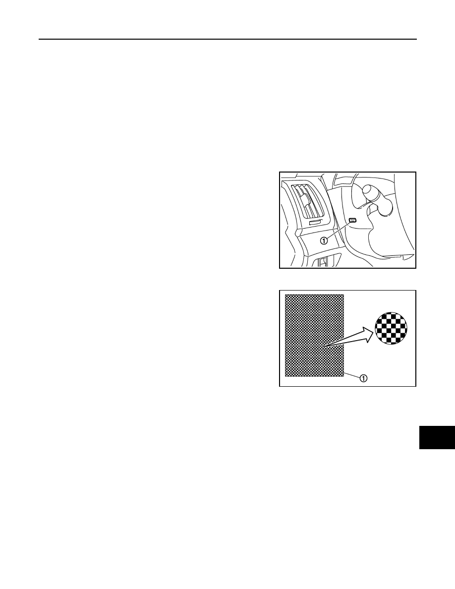
1.
Turn ignition switch ON, and switch the trip meter to “trip A” or “trip B”.
NOTE:
If the diagnosis function is activated with “trip A” displayed, the mileage on “trip A” is reset to “0000.0”.
(The same way for “trip B”.)
2.
Turn ignition switch OFF.
3.
While pressing the trip A/B reset switch (1), turn ignition switch
ON again.
4.
Make sure that the trip meter displays “0000.0”.
5.
Press the trip A/B reset switch at least 3 times. (Within 7 sec-
onds after the ignition switch is turned ON.)
6.
The unified meter control unit is turned to self-diagnosis mode.
• Displays "888888" and "8888.8" in the information display LCD
(1) for approximately 5 seconds and then blinks the segment
dots of the information display LCD alternately.
• Water temperature gauge and fuel gauge return to zero, and
at the same time.
NOTE:
• Check combination meter power supply and ground circuit when self-diagnosis mode of combination
meter does not start. Replace combination meter if normal.
• If any of the segments is not displayed, replace combination meter.
JSNIA0019GB
JSNIA0020GB