Infiniti G35 (V35) Sedan. Manual - part 796


  Index      Infiniti     Infiniti G35 (V35) Sedan - service repair manual 2007 year


Search            


Content   ..  794  795  796  797   ..


Infiniti G35 (V35) Sedan. Manual - part 796


INL-12

< FUNCTION DIAGNOSIS >

ILLUMINATION CONTROL SYSTEM

Component Description

INFOID:0000000000962576

1.

Combination switch

2.

Illumination control switch

3.

Combination meter

4.

BCM

5.

IPDM E/R

6.

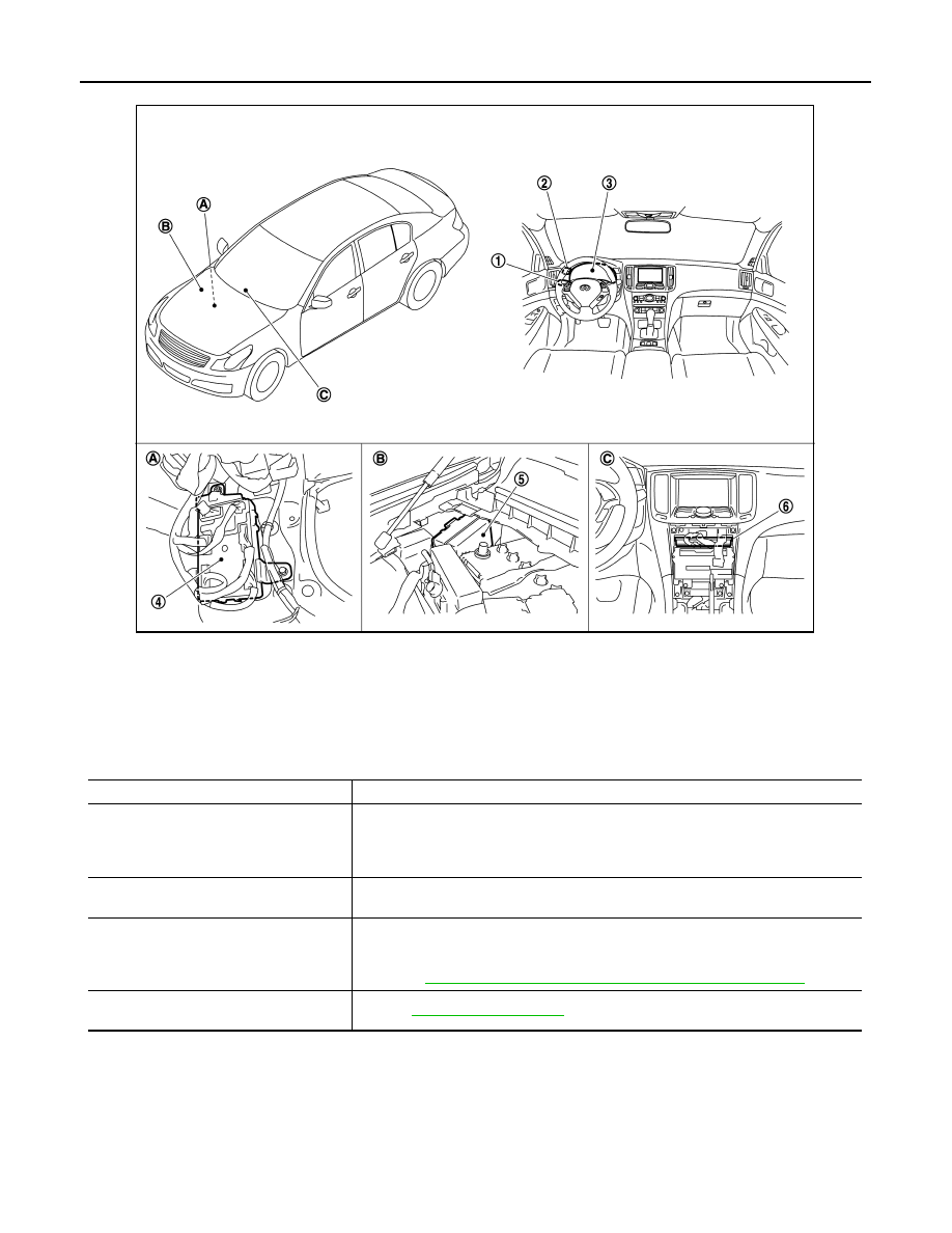
Unified meter and A/C amp.

A

Dash side finisher (Passenger side)

B.

Engine room dash panel (RH)

C.

Behind cluster lid C

JPLIA0040ZZ

Part

Description

BCM

• Judges each switch condition by the combination switch reading function.
• Judges the illumination lamp ON/OFF status depending on the vehicle condition. 

And then it transmits position light request signal to IPDM E/R and combination 
meter (through the unified meter and A/C amp.) (with CAN communication). 

IPDM E/R

Controls the integrated relay according to the request from BCM (with CAN communi-
cation).

COMBINATION METETR

• Enters in nighttime mode according to the request from BCM (with CAN communi-

cation).

• Controls the each illumination in the nighttime mode.

Refer to 

MWI-24, "METER ILLUMINATION CONTROL : System Diagram"

.

Combination switch
(Lighting & turn signal switch)

Refer to 

BCS-5, "System Diagram"

.

DIAGNOSIS SYSTEM (BCM)

INL-13

< FUNCTION DIAGNOSIS >

C

D

E

F

G

H

I

J

K

M

A

B

INL

N

O

P

DIAGNOSIS SYSTEM (BCM)

COMMON ITEM

COMMON ITEM : CONSULT-III Function (BCM - COMMON ITEM)

INFOID:0000000000962577

APPLICATION ITEM

CONSULT-III performs the following functions via CAN communication with BCM.

SYSTEM APPLICATION

BCM can perform the following functions for each system.
NOTE:
It can perform the diagnosis modes except the following for all sub system selection items.

*: This item is displayed, but is not used. 

INT LAMP

INT LAMP : CONSULT-III Function (BCM - INT LAMP)

INFOID:0000000000962578

Diagnosis mode

Function Description

WORK SUPPORT

Changes the setting for each system function.

SELF-DIAG RESULTS

Displays the diagnosis results judged by BCM. Refer to 

INL-77, "DTC Index"

.

CAN DIAG SUPPORT MNTR

Monitors the reception status of CAN communication viewed from BCM.

DATA MONITOR

The BCM input/output signals are displayed.

ACTIVE TEST

The signals used to activate each device are forcibly supplied from BCM.

ECU IDENTIFICATION

The BCM part number is displayed.

CONFIGURATION

This function is not used even though it is displayed.

System

Sub system selection item

Diagnosis mode

WORK SUPPORT

DATA MONITOR

ACTIVE TEST

Door lock

DOOR LOCK

×

×

×

Rear window defogger

REAR DEFOGGER

×

×

Warning chime

BUZZER

×

×

Interior room lamp timer

INT LAMP

×

×

×

Exterior lamp

HEAD LAMP

×

×

×

Wiper and washer

WIPER

×

×

×

Turn signal and hazard warning lamps

FLASHER

×

×

×

Air conditioner*

AIR CONDITONER

×

Intelligent Key system

INTELLIGENT KEY

×

×

×

Combination switch

COMB SW

×

BCM

BCM

×

IVIS - NATS

IMMU

×

×

Interior room lamp battery saver

BATTERY SAVER

×

×

×

Trunk open

TRUNK

×

Vehicle security system

THEFT ALM

×

×

×

RAP system

RETAINED PWR

×

Signal buffer system

SIGNAL BUFFER

×

×

TPMS

TPMS (AIR PRESSURE MONI-
TOR)

×

×

×

INL-14

< FUNCTION DIAGNOSIS >

DIAGNOSIS SYSTEM (BCM)

WORK SUPPORT

*: Initial setting

DATA MONITOR

JPLIA0093GB

Service item

Setting item

Setting

ROOM LAMP TIMER SET

MODE 2

7.5 sec.

Sets the interior room lamp ON time. (Timer operating time)

MODE 3*

15 sec.

MODE 4

30 sec.

SET I/L D-UNLCK INTCON

ON*

With the interior room lamp timer function

OFF

Without the interior room lamp timer function

ROOM LAMP ON TIME SET

MODE 1

0.5 sec.

Sets the interior room lamp gradual brightening time.

MODE 2*

1 sec.

MODE 3

2 sec.

MODE 4

3 sec.

MODE 5

0 sec.

ROOM LAMP OFF TIME SET

MODE 1

0.5 sec.

Sets the interior room lamp gradual dimming time.

MODE 2

1 sec.

MODE 3

2 sec.

MODE 4*

3 sec.

MODE 5

0 sec.

R LAMP TIMER LOGIC SET

ON*

Interior room lamp timer activates with synchronizing all doors.

OFF

Interior room lamp timer activates with synchronizing the driver door 
only.

Monitor item

[Unit]

Description

REQ SW-DR
[ON/OFF]

The switch status input from request switch (driver side)

REQ SW-AS
[ON/OFF]

The switch status input from front request switch (passenger side)

PUSH SW
[ON/OFF]

The switch status input from push-button ignition switch

ACC RLY-F/B
[ON/OFF]

ACC relay feedback signal status input from ACC relay

KEY SW-SLOT
[ON/OFF]

Key switch status input from key slot

DIAGNOSIS SYSTEM (BCM)

INL-15

< FUNCTION DIAGNOSIS >

C

D

E

F

G

H

I

J

K

M

A

B

INL

N

O

P

ACTIVE TEST

BATTERY SAVER

BATTERY SAVER : CONSULT-III Function (BCM - BATTERY SAVER)

INFOID:0000000000962579

WORK SUPPORT

*: Initial setting

DATA MONITOR

DOOR SW-DR
[ON/OFF]

The switch status input from front door switch (driver side)

DOOR SW-AS
[ON/OFF]

The switch status input from front door switch (passenger side)

DOOR SW-RR
[ON/OFF]

The switch status input from rear door switch RH

DOOR SW- RL
[ON/OFF]

The switch status input from rear door switch LH

DOOR SW-BK
[ON/OFF]

NOTE:
The item is indicated, but not monitored.

CDL LOCK SW
[ON/OFF]

Lock switch status received from central door lock switch by power window switch se-
rial link

CDL UNLOCK SW
[ON/OFF]

Unlock switch status received from central door lock switch by power window switch 
serial link

KEY CYL LK-SW
[ON/OFF]

Lock switch status received from key cylinder switch by power window switch serial 
link

KEY CYL UN-SW
[ON/OFF]

Unlock switch status received from key cylinder switch by power window switch serial 
link

TRNK/HAT MNTR
[ON/OFF]

The switch status input from trunk room lamp switch

RKE-LOCK
[ON/OFF]

Lock signal status received from remote keyless entry receiver

RKE-UNLOCK
[ON/OFF]

Unlock signal status received from remote keyless entry receiver

Monitor item

[Unit]

Description

Test item

Operation

Description

INT LAMP

ON

Outputs the interior room lamp control signal to turn map lamp and personal lamp ON 
(Map lamp switch is in DOOR position).

OFF

Stops the interior room lamp control signal to turn map lamp and personal lamp OFF.

STEP LAMP TEST

ON

Outputs the step lamp control signal to turn step lamp ON.

OFF

Stops the step lamp control signal to turn step lamp OFF.

LUGGAGE LAMP TEST

ON

Outputs the trunk room lamp control signal to turn step lamp ON.

OFF

Stops the trunk room lamp control signal to turn step lamp ON.

Service item

Setting item

Setting

BATTERY SAVER SET

ON*

With the exterior lamp battery saver function

OFF

Without the exterior lamp battery saver function

ROOM LAMP BAT SAV SET

ON*

With the interior room lamp battery saver function

OFF

Without the interior room lamp battery saver function

ROOM LAMP TIMER SET

MODE 1*

30 min.

Sets the interior room lamp battery saver timer operating 
time. 

MODE 2

60 min.


Content   ..  794  795  796  797   ..