Infiniti G35 (V35) Sedan. Manual - part 781


  Index      Infiniti     Infiniti G35 (V35) Sedan - service repair manual 2007 year


Search            


Content   ..  779  780  781  782   ..


Infiniti G35 (V35) Sedan. Manual - part 781


HAC-96

< COMPONENT DIAGNOSIS >

[AUTOMATIC AIR CONDITIONER]

IN-VEHICLE SENSOR

IN-VEHICLE SENSOR

Description

INFOID:0000000000959956

In-vehicle Sensor
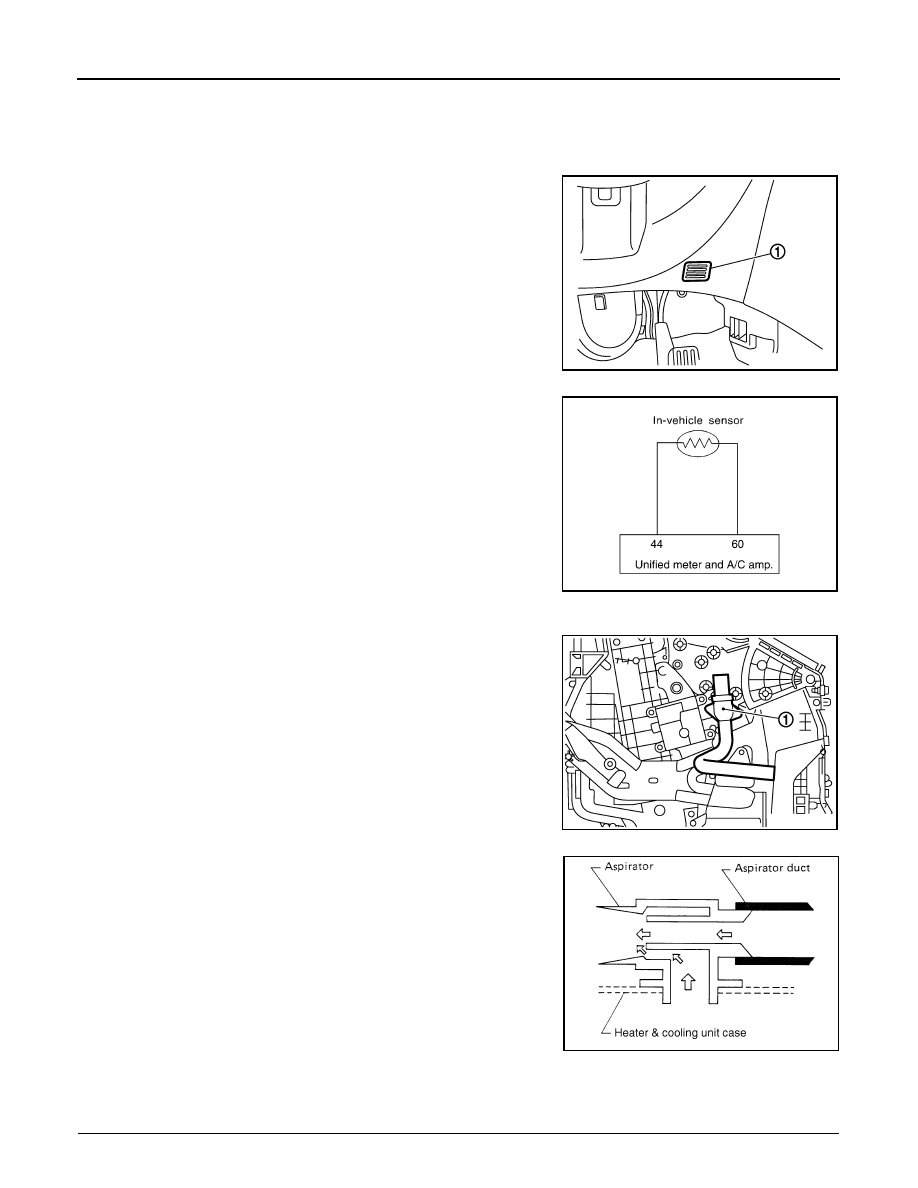
The in-vehicle sensor (1) is located on instrument driver lower panel.
It converts variations in temperature of compartment air drawn from
the aspirator into a resistance value. It is then input into the unified
meter and A/C amp.

In-vehicle Sensor Circuit

Aspirator
The aspirator (1) is located on driver’s side of heater & cooling unit
assembly. It produces vacuum pressure due to air discharged from
the heater & cooling unit assembly, continuously taking compartment
air in the aspirator.

Component Function Check

INFOID:0000000000959957

1.

PERFORM SELF-DIAGNOSIS STEP-2

JSIIA0048ZZ

RJIA4094E

JSIIA0100ZZ

RJIA1804E

IN-VEHICLE SENSOR

HAC-97

< COMPONENT DIAGNOSIS >

[AUTOMATIC AIR CONDITIONER]

C

D

E

F

G

H

J

K

L

M

A

B

HAC

N

O

P

Perform self-diagnosis STEP-2. Refer to 

HAC-44, "WITHOUT LEFT AND RIGHT VENTILATION TEMPERA-

TURE SEPARATELY CONTROL SYSTEM : Diagnosis Description"

 (Without left and right ventilation tempera-

ture separately control system) or 

HAC-50, "WITH LEFT AND RIGHT VENTILATION TEMPERATURE

SEPARATELY CONTROL SYSTEM : Diagnosis Description"

 (With left and right ventilation temperature sepa-

rately control system), see No. 1 to 2.
22 or –22 is displayed.

YES

>> Go to Diagnosis Procedure. Refer to 

HAC-97, "Diagnosis Procedure"

.

NO

>> END.

Diagnosis Procedure

INFOID:0000000000959958

1.

CHECK VOLTAGE BETWEEN IN-VEHICLE SENSOR AND GROUND

1.

Disconnect in-vehicle sensor connector.

2.

Turn ignition switch ON.

3.

Check voltage between in-vehicle sensor harness connector M61 terminal 1 and ground.

Is the inspection result normal?

YES

>> GO TO 2.

NO

>> GO TO 4.

2.

CHECK CIRCUIT CONTINUITY BETWEEN IN-VEHICLE SENSOR AND UNIFIED METER AND A/C AMP.

1.

Turn ignition switch OFF.

2.

Disconnect unified meter and A/C amp. connector.

3.

Check continuity between in-vehicle sensor harness connector M61 terminal 2 and unified meter and A/C
amp. harness connector M67 terminal 60.

Is the inspection result normal?

YES

>> GO TO 3.

NO

>> Repair harness or connector.

3.

CHECK IN-VEHICLE SENSOR

Refer to 

HAC-98, "Component Inspection"

.

Is the inspection result normal?

YES

>> Replace unified meter and A/C amp.

NO

>> Replace in-vehicle sensor.

4.

CHECK CIRCUIT CONTINUITY BETWEEN IN-VEHICLE SENSOR AND UNIFIED METER AND A/C AMP.

1.

Turn ignition switch OFF.

2.

Disconnect unified meter and A/C amp. connector.

3.

Check continuity between in-vehicle sensor harness connector M61 terminal 1 and unified meter and A/C
amp. harness connector M67 terminal 44.

(+)

(

)

Voltage

In-vehicle sensor

Connector

Terminal

M61

1

Ground

Approx. 5 V

(+)

(

)

Continuity

In-vehicle sensor

Unified meter and A/C amp.

Connector

Terminal

Connector

Terminal

M61

2

M67

60

Continuity should exist

(+)

(

)

Continuity

In-vehicle sensor

Unified meter and A/C amp.

Connector

Terminal

Connector

Terminal

M61

1

M67

44

Continuity should exist

HAC-98

< COMPONENT DIAGNOSIS >

[AUTOMATIC AIR CONDITIONER]

IN-VEHICLE SENSOR

4.

Check continuity between in-vehicle sensor harness connector M61 terminal 1 and ground.

Is the inspection result normal?

YES

>> Replace unified meter and A/C amp.

NO

>> Repair harness or connector.

Component Inspection

INFOID:0000000000959959

After disconnecting in-vehicle sensor (1) connector M61, measure
resistance between terminals 1 and 2 at sensor side. Refer to table
below.

If NG, replace in-vehicle sensor.

(+)

(

)

Continuity

In-vehicle sensor

Connector

Terminal

M61

1

Ground

Continuity should not exist

Temperature 

°

C (

°

F)

Resistance k


15 (5)

12.73


10 (14)

9.92


5 (23)

7.80

0 (32)

6.19

5 (41)

4.95

10 (50)

3.99

15 (59)

3.24

20 (68)

2.65

25 (77)

2.19

30 (86)

1.81

35 (95)

1.51

40 (104)

1.27

45 (113)

1.07

JSIIA0049ZZ

SUNLOAD SENSOR

HAC-99

< COMPONENT DIAGNOSIS >

[AUTOMATIC AIR CONDITIONER]

C

D

E

F

G

H

J

K

L

M

A

B

HAC

N

O

P

SUNLOAD SENSOR

Description

INFOID:0000000000959960

COMPONENT DESCRIPTION

Sunload Sensor

The sunload sensor (1) is located on the driver’s side front defroster
grille. It detects sunload entering through windshield by means of a
photo diode. The sensor converts the sunload into a current value
which is then input into the unified meter and A/C amp.

Sunload Sensor Circuit

SUNLOAD INPUT PROCESS

The unified meter and A/C amp. also includes a processing circuit which averages the variations in detected
sunload over a period of time. This prevents drastic swings in the ATC system operation due to small or quick
variations in detected sunload.
For example, consider driving along a road bordered by an occasional group of large trees. The sunload
detected by the sunload sensor will vary whenever the trees obstruct the sunlight. The processing circuit aver-
ages the detected sunload over a period of time, so that the (insignificant) effect of the trees momentarily
obstructing the sunlight does not cause any change in the ATC system operation. On the other hand, shortly
after entering a long tunnel, the system will recognize the change in sunload, and the system will react accord-
ingly.

Component Function Check

INFOID:0000000000959961

1.

PERFORM SELF-DIAGNOSIS STEP-2

Perform self-diagnosis STEP-2. Refer to 

HAC-44, "WITHOUT LEFT AND RIGHT VENTILATION TEMPERA-

TURE SEPARATELY CONTROL SYSTEM : Diagnosis Description"

 (Without left and right ventilation tempera-

ture separately control system) or 

HAC-50, "WITH LEFT AND RIGHT VENTILATION TEMPERATURE

SEPARATELY CONTROL SYSTEM : Diagnosis Description"

 (With left and right ventilation temperature sepa-

rately control system), see No. 1 to 2.

25 or 

25 is displayed.

YES

>> Go to Diagnosis Procedure. Refer to 

HAC-99, "Diagnosis Procedure"

.

NO

>> END.

Diagnosis Procedure

INFOID:0000000000959962

1.

CHECK VOLTAGE BETWEEN SUNLOAD SENSOR AND GROUND

1.

Disconnect sunload sensor connector.

2.

Turn ignition switch ON.

JSIIA0050ZZ

RJIA4099E


Content   ..  779  780  781  782   ..