Infiniti G35 (V35) Sedan. Manual - part 734
 

  Index      Infiniti     Infiniti G35 (V35) Sedan - service repair manual 2007 year


Search            


Content   ..  732  733  734  735   ..


Infiniti G35 (V35) Sedan. Manual - part 734


GI-46

< BASIC INSPECTION >

SERVICE INFORMATION FOR ELECTRICAL INCIDENT

INPUT-OUTPUT VOLTAGE CHART

• The voltage value is based on the body ground.

• *: If high resistance exists in the switch side circuit (caused by a single strand), terminal 1 does not detect battery voltage. Control unit

does not detect the switch is ON even if the switch does not turn ON. Therefore, the control unit does not supply power to light up the
lamp.

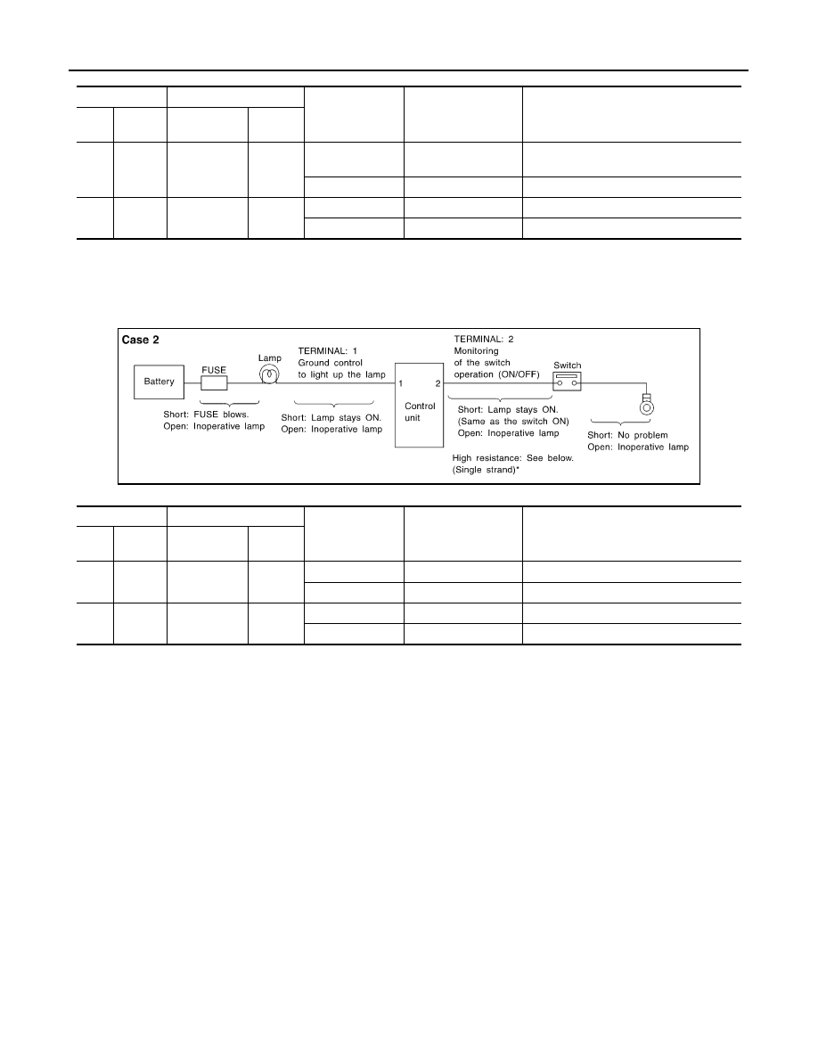
CASE 2

INPUT-OUTPUT VOLTAGE CHART

• The voltage value is based on the body ground.

• *: If high resistance exists in the switch side circuit (caused by a single strand), terminal 2 does not detect approx. 0V. Control unit

does not detect the switch is ON even if the switch does not turn ON. Therefore, the control unit does not control ground to light up the
lamp.

Terminal No.

Description

Condition

Value (Approx.)

In case of high resistance such as single 
strand (V) *

+

Signal name

Input/

Output

1

Body 
ground

Switch

Input

Switch ON

Battery voltage

Lower than battery voltage Approx. 8 (Ex-
ample)

Switch OFF

0 V

Approx. 0

2

Body 
ground

Lamp

Output

Switch ON

Battery voltage

Approx. 0 (Inoperative lamp)

Switch OFF

0 V

Approx. 0

Terminal No.

Description

Condition

Value (Approx.)

In case of high resistance such as single 
strand (V) *

+

Signal name

Input/

Output

1

Body 
ground

Lamp

Output

Switch ON

0V

Battery voltage (Inoperative lamp)

Switch OFF

Battery voltage

Battery voltage

2

Body 
ground

Switch

Input

Switch ON

0 V

Higher than 0 Approx. 4 (Example)

Switch OFF

5 V

Approx. 5

MGI035A

CONSULT-III CHECKING SYSTEM

GI-47

< BASIC INSPECTION >

C

D

E

F

G

H

I

J

K

L

M

B

GI

N

O

P

CONSULT-III CHECKING SYSTEM

Description

INFOID:0000000000956206

• When CONSULT-III is connected with a data link connector (A)

equipped on the vehicle side, it will communicate with the control
unit equipped in the vehicle and then enable various kinds of diag-
nostic tests.

• Refer to “CONSULT-III Software Operation Manual” for more infor-

mation.

Function and System Application

INFOID:0000000000956207

1

: Instrument driver lower panel

JPAIA0024ZZ

Diagnostic test 

mode

Function

ENGINE

A/

T

AIR B

A

G

MET

E

R/M

&

A

BC

M

AUT

O

 DRIVE 

POS.

ABS (I

nc

lu

di

n

g

 VDC)

IPDM E/R

ICC

ALL MODE 

A

W

D/4WD

4W

AS

(FRONT

)

4W

AS(MAIN)/RAS

/HICAS

ADAP

TIVE

 LI

GHT

MUL

T

I A

V

Work support

This mode enables a technician to adjust 
some devices faster and more accurately by 
following the indications on CONSULT-III.

x

x

-

-

x

x

x

-

x

-

-

-

x

-

Self-diagnostic 
results

Self-diagnostic results can be read and 
erased quickly.

x

x

x

x

x

x

x

x

x

x

x

x

x

x

Trouble diagnos-
tic record

Current self-diagnostic results and all trouble 
diagnostic records previously stored can be 
read.

-

-

x

-

-

-

-

-

-

-

-

-

-

-

Data  monitor

Input/Output  data  in  the  ECU  can  be  read.

x

x

-

x

x

x

x

x

x

x

x

x

x

x

CAN diagnosis

The condition of CAN communication line can 
be indicated by a topology.

x

x

x

x

x

x

x

x

x

x

-

x

x

x

CAN diagnosis 
support monitor

The condition of CAN communication line can 
be read.

x

x

-

x

x

x

x

x

x

x

x

x

x

x

Active test

Diagnostic Test Mode in which CONSULT-III 
drives some actuators apart from the ECUs 
and also shifts some parameters in a speci-
fied range.

x

-

-

-

x

x

x

x

x

x

x

x

x

-

DTC & SRT con-
firmation

The results of SRT (System Readiness Test) 
and the self-diagnosis status/result can be 
confirmed.

x

-

-

-

-

-

-

-

-

-

-

-

-

-

DTC work sup-
port

The operating condition to confirm Diagnosis 
Trouble Codes can be selected.

-

x

-

-

-

-

-

-

-

-

-

-

-

-

ECU (ECM/TCM) 
part number

ECU  (ECM/TCM)  part  number  can  be  read.

x

x

-

-

x

x

x

-

x

x

x

x

x

x

ECU discriminat-
ed No.

Classification number of a replacement ECU 
can be read to prevent an incorrect ECU from 
being installed.

-

-

x

-

-

-

-

-

-

-

-

-

-

-

GI-48

< BASIC INSPECTION >

CONSULT-III CHECKING SYSTEM

x: Applicable

CONSULT-III Data Link Connector (DLC) Circuit

INFOID:0000000000956208

INSPECTION PROCEDURE

If the CONSULT-III cannot diagnose the system properly, check the following items.

NOTE:
The DDL1 and DDL2 circuits from DLC pins 12, 13, 14 and 15 may be connected to more than one system. A
short in a DDL circuit connected to a control unit in one system may affect CONSULT-III access to other sys-
tems.

Function test

This mode can show results of self-diagnosis 
of ECU with either 'OK' or 'NG'. For engines, 
more practical tests regarding sensors/
switches and/or actuators are available.

x

x

x

-

-

-

x

-

-

-

-

-

-

-

Configration

Function to READ/WRITE vehicle configura-
tion on BCM.

-

-

-

-

x

-

-

-

-

-

-

-

-

-

AV COMM moni-
tor

The condition of AV communication can be In-
dicated.

-

-

-

-

-

-

-

-

-

-

-

-

-

x

Diagnostic test 

mode

Function

ENGINE

A/

T

AIR BAG

METER/M

&

A

BCM

AUT

O

 DRIV

E

 POS.

ABS (Includi

ng 

VDC)

IP

DM E/

R

ICC

ALL MODE A

W

D/4WD

4W

AS(F

R

ONT)

4W

AS(MA

IN)/RAS/HI

C

A

S

ADAP

T

IVE LIGHT

MUL

T

I A

V

Symptom

Check item

CONSULT-III cannot access 
any system.

• CONSULT-III DLC power supply circuit (Terminal 8) and ground circuit (Terminal 4) 

CONSULT-III cannot access in-
dividual system. (Other sys-
tems can be accessed.)

• Power supply and ground circuit for the control unit of the system (For detailed circuit, refer to wiring 

diagram for each system.)

• Open or short circuit between the system and CONSULT-III DLC (For detailed circuit, refer to wiring 

diagram for each system.)

• Open or short circuit CAN communication line. Refer to 

LAN-18, "Trouble Diagnosis Flow Chart"

.

CONSULT-III CHECKING SYSTEM

GI-49

< BASIC INSPECTION >

C

D

E

F

G

H

I

J

K

L

M

B

GI

N

O

P

Wiring Diagram - CONSULT-III CHECKING SYSTEM -

INFOID:0000000000956209

JCAWA0001GB


Content   ..  732  733  734  735   ..