Infiniti G35 (V35) Sedan. Manual - part 686
EXL-186
< ON-VEHICLE REPAIR >
[XENON TYPE]
FRONT COMBINATION LAMP
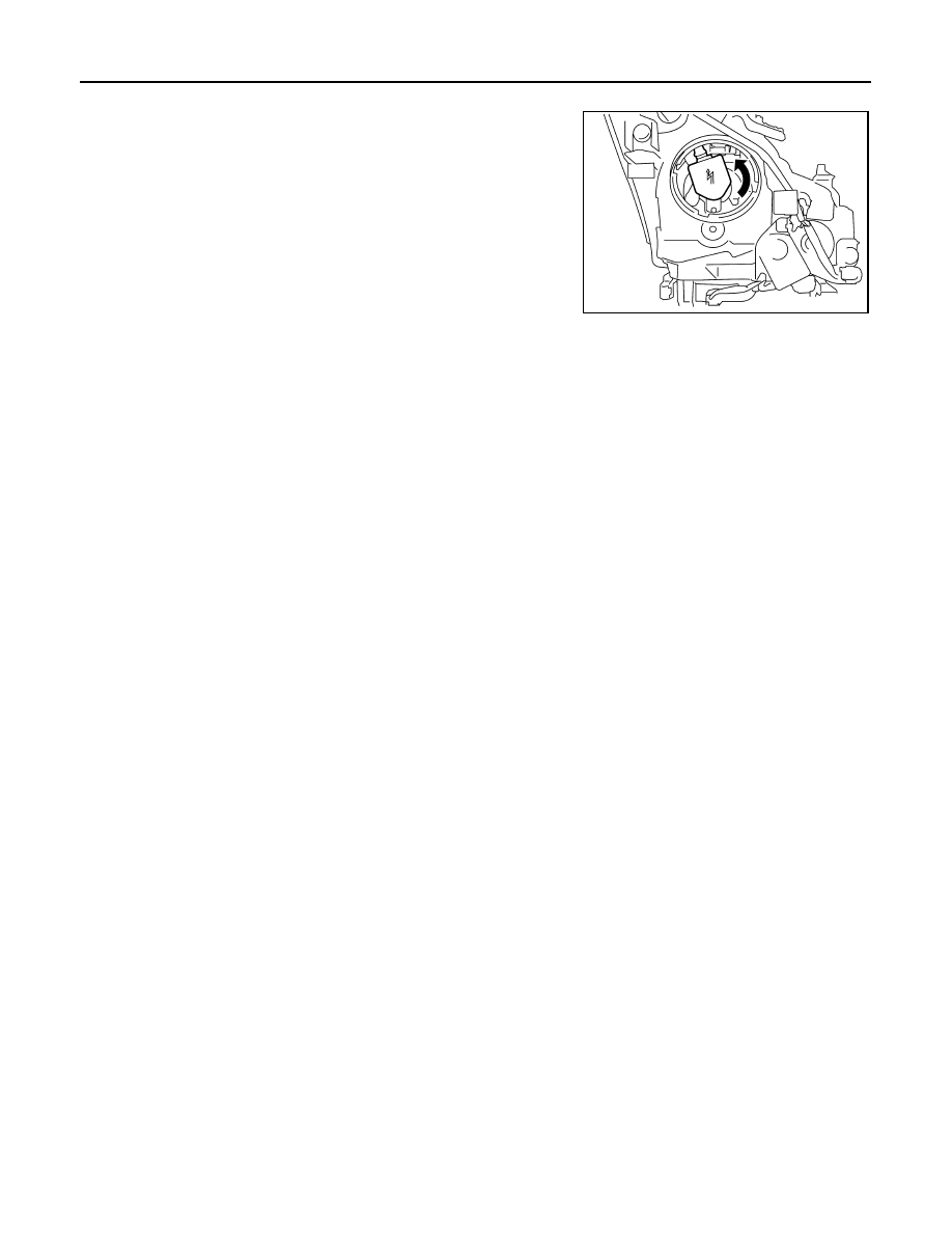
2.
Rotate the resin cap counterclockwise and unlock it.
3.
Rotate the bulb socket counterclockwise and unlock it.
4.
Remove the retaining spring lock. Remove the bulb from the
headlamp.
CAUTION:
Never break the xenon bulb ceramic tube when replacing
the bulb.
PARKING LAMP BULB
1.
Remove the fender protector. Keep a service area.
2.
Rotate the bulb socket counterclockwise and unlock it.
3.
Remove the bulb from the bulb socket.
FRONT TURN SIGNAL LAMP BULB
1.
Remove the air cleaner case.
2.
Rotate the bulb socket counterclockwise and unlock it.
3.
Remove the bulb from the bulb socket.
FRONT FOG LAMP BULB
1.
Remove the air cleaner case.
2.
Remove the front fog lamp bulb connector.
3.
Rotate the bulb socket counterclockwise and unlock it.
Disassembly and Assembly
INFOID:0000000000962535
DISASSEMBLY
1.
Rotate the resin cap counterclockwise and unlock it.
2.
Rotate the xenon bulb socket counterclockwise and unlock it.
3.
Remove the retaining spring lock. Remove the xenon bulb.
4.
Remove the HID control unit installation screw.
5.
Remove the screw. Disconnect the connector from HID control unit.
6.
Pull out the xenon bulb socket from the headlamp housing assembly.
7.
Rotate the parking lamp bulb socket counterclockwise and unlock it.
8.
Remove the bulb from the parking lamp bulb socket.
9.
Rotate the front turn signal lamp bulb socket counterclockwise and unlock it.
10. Remove the bulb from the front turn signal lamp bulb socket.
11. Rotate the front fog lamp bulb socket counterclockwise. Remove the bulb.
ASSEMBLY
Assemble in the reverse order of disassembly.
CAUTION:
• Install HID control unit securely.
• After installing the bulb, install the resin cap and the bulb socket securely for watertightness.
Adjustment
INFOID:0000000000962536
PREPARATION BEFORE ADJUSTING
NOTE:
• For details, refer to the regulations in your own country.
• Perform aiming if the vehicle front body has been repaired and/or the headlamp assembly has been
replaced.
JPLIA0044ZZ