Infiniti G35 (V35) Sedan. Manual - part 611


  Index      Infiniti     Infiniti G35 (V35) Sedan - service repair manual 2007 year


Search            


Content   ..  609  610  611  612   ..


Infiniti G35 (V35) Sedan. Manual - part 611


OIL PAN (LOWER)

EM-43

< ON-VEHICLE REPAIR >

C

D

E

F

G

H

I

J

K

L

M

A

EM

N

P

O

a.

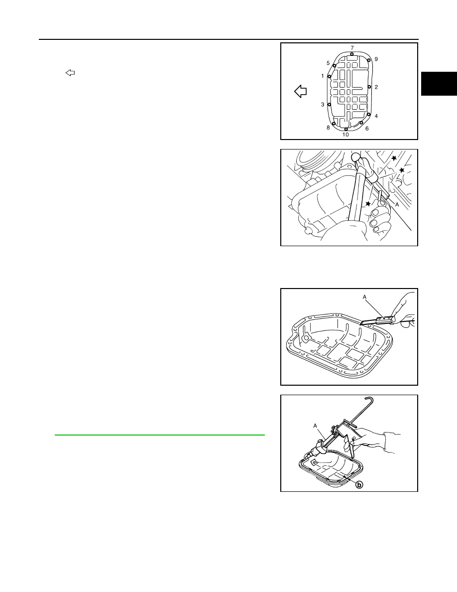
Loosen mounting bolts in reverse order as shown in the figure to
remove.

b.

Insert the seal cutter [SST: KV10111100 (J37228)] (A) between
oil pan (upper) and oil pan (lower).

CAUTION:

• Be careful not to damage the mating surfaces.
• Do not insert a screwdriver, this will damage the mating

surfaces.

c.

Slide the seal cutter by tapping on the side of tool with a ham-
mer. Remove oil pan (lower).

INSTALLATION

1.

Install oil pan (lower) as follows:

a.

Use scraper (A) to remove old liquid gasket from mating sur-
faces.
• Remove old liquid gasket from the bolt holes and thread.

CAUTION:

Do not scratch or damage the mating surfaces when clean-
ing off old liquid gasket.

b.

Apply a continuous bead of liquid gasket with the tube presser
[SST: WS39930000 (

)] (A) to the oil pan (lower) as shown

in the figure.
Use Genuine RTV Silicone Sealant or equivalent. Refer to

GI-15, "Recommended Chemical Products and Sealants"

.

CAUTION:

Attaching should be done within 5 minutes after coating.

c.

Install oil pan (lower).

: Engine front

JPBIA0021ZZ

JPBIA0276ZZ

JPBIA0025ZZ

b

: 4.0 - 5.0 mm (0.157 - 0.197 in)

JPBIA0026ZZ

EM-44

< ON-VEHICLE REPAIR >

OIL PAN (LOWER)

• Tighten mounting bolts in numerical order as shown in the fig-

ure.

2.

Install oil pan drain plug.
• Refer to the figure of components of former page for installation direction of drain plug washer. Refer to

EM-41, "Exploded View (2WD)"

 and 

EM-41, "Exploded View (AWD)"

.

3.

Install in the reverse order of removal after this step.
NOTE:
At least 30 minutes after oil pan is installed, pour engine oil.

Inspection

INFOID:0000000000956253

INSPECTION AFTER REMOVAL

Clean oil strainer if any object attached.

INSPECTION AFTER INSTALLATION

1.

Check the engine oil level and adjust engine oil. Refer to 

LU-7, "Inspection"

.

2.

Start engine, and check there is no leak of engine oil.

3.

Stop engine and wait for 10 minutes.

4.

Check the engine oil level again. Refer to 

LU-7, "Inspection"

.

: Engine front

JPBIA0021ZZ

IGNITION COIL, SPARK PLUG AND ROCKER COVER

EM-45

< ON-VEHICLE REPAIR >

C

D

E

F

G

H

I

J

K

L

M

A

EM

N

P

O

IGNITION COIL, SPARK PLUG AND ROCKER COVER

Exploded View

INFOID:0000000000956254

Removal and Installation

INFOID:0000000000956255

REMOVAL

1.

Remove the following parts:
• Engine cover: Refer to 

EM-27, "Exploded View"

.

• Air cleaner case and air duct (RH and LH): Refer to 

EM-25, "Exploded View"

.

• Intake manifold collector: Refer to 

EM-27, "Exploded View"

.

2.

Disconnect PCV hose from rocker cover.

1.

PCV hose

2.

Clamp

3.

Ignition coil

4.

Spark plug

5.

PCV valve

6.

O-ring

7.

Rocker cover gasket (right bank)

8.

Rocker cover (right bank)

9.

O-ring

10.

Camshaft position sensor (PHASE) 
(bank 1)

11.

Exhaust valve timing control position 
sensor (bank 1)

12.

Camshaft position sensor (PHASE) 
(bank 2)

13.

Exhaust valve timing control position 
sensor (bank 2)

14.

Rocker cover gasket (left bank)

15. Rocker cover (left bank)

16.

PCV hose

17.

Oil catcher

18. Oil filler cap

19.

PCV hose

A.

To intake manifold collector

B.

Refer to 

EM-45

C.

Camshaft bracket side

D.

To air duct

Refer to 

GI-4, "Components"

 for symbol marks in the figure.

JPBIA0009ZZ

EM-46

< ON-VEHICLE REPAIR >

IGNITION COIL, SPARK PLUG AND ROCKER COVER

3.

Remove camshaft position sensor (PHASE) and exhaust valve
timing control position sensor (bank 1 and bank 2).

CAUTION:

• Handle carefully to avoid dropping and shocks.
• Do not disassemble
• Do not allow metal powder to adhere to magnetic part at

sensor tip. 

• Do not place sensors in a location where they are

exposed to magnetism.

4.

Remove PCV valve and O-ring from rocker cover, if necessary.

5.

Remove oil filler cap from rocker cover, if necessary. 

6.

Remove ignition coil.

CAUTION:

Do not shock it.

7.

Remove harness clips on the rocker cover.

8.

Loosen bolts in reverse order shown in the figure.

9.

Remove rocker cover gasket from rocker cover.

10. Use scraper to remove all traces of liquid gasket from cylinder

head and camshaft bracket (No. 1).

CAUTION:

Do not scratch or damage the mating surface when clean-
ing off old liquid gasket.

INSTALLATION

A

: Keep off any magnetic materials

: Engine front

JPBIA0454ZZ

JPBIA0040ZZ


Content   ..  609  610  611  612   ..