Infiniti G35 (V35) Sedan. Manual - part 599
EC-542
< PREPARATION >
[VQ35HR]
PREPARATION
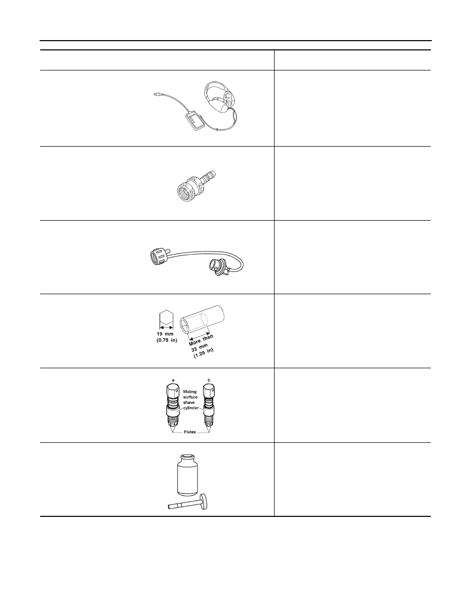
Tool name
(Kent-Moore No.)
Description
Leak detector
i.e.: (J-41416)
Locating the EVAP leak
EVAP service port
adapter
i.e.: (J-41413-OBD)
Applying positive pressure through EVAP service
port
Fuel filler cap adapter
i.e.: (MLR-8382)
Checking fuel tank vacuum relief valve opening
pressure
Socket wrench
Removing and installing engine coolant tempera-
ture sensor
Oxygen sensor thread
cleaner
i.e.: (J-43897-18)
(J-43897-12)
Reconditioning the exhaust system threads before
installing a new oxygen sensor. Use with anti-
seize lubricant shown below.
a: 18 mm diameter with pitch 1.5 mm for Zirco-
nia Oxygen Sensor
b: 12 mm diameter with pitch 1.25 mm for Tita-
nia Oxygen Sensor
Anti-seize lubricant
i.e.: (Permatex
TM
133AR or equivalent
meeting MIL specifica-
tion MIL-A-907)
Lubricating oxygen sensor thread cleaning tool
when reconditioning exhaust system threads.
S-NT703
S-NT704
S-NT815
S-NT705
AEM488
S-NT779