Infiniti G35 (V35) Sedan. Manual - part 530
EC-266
< COMPONENT DIAGNOSIS >
[VQ35HR]
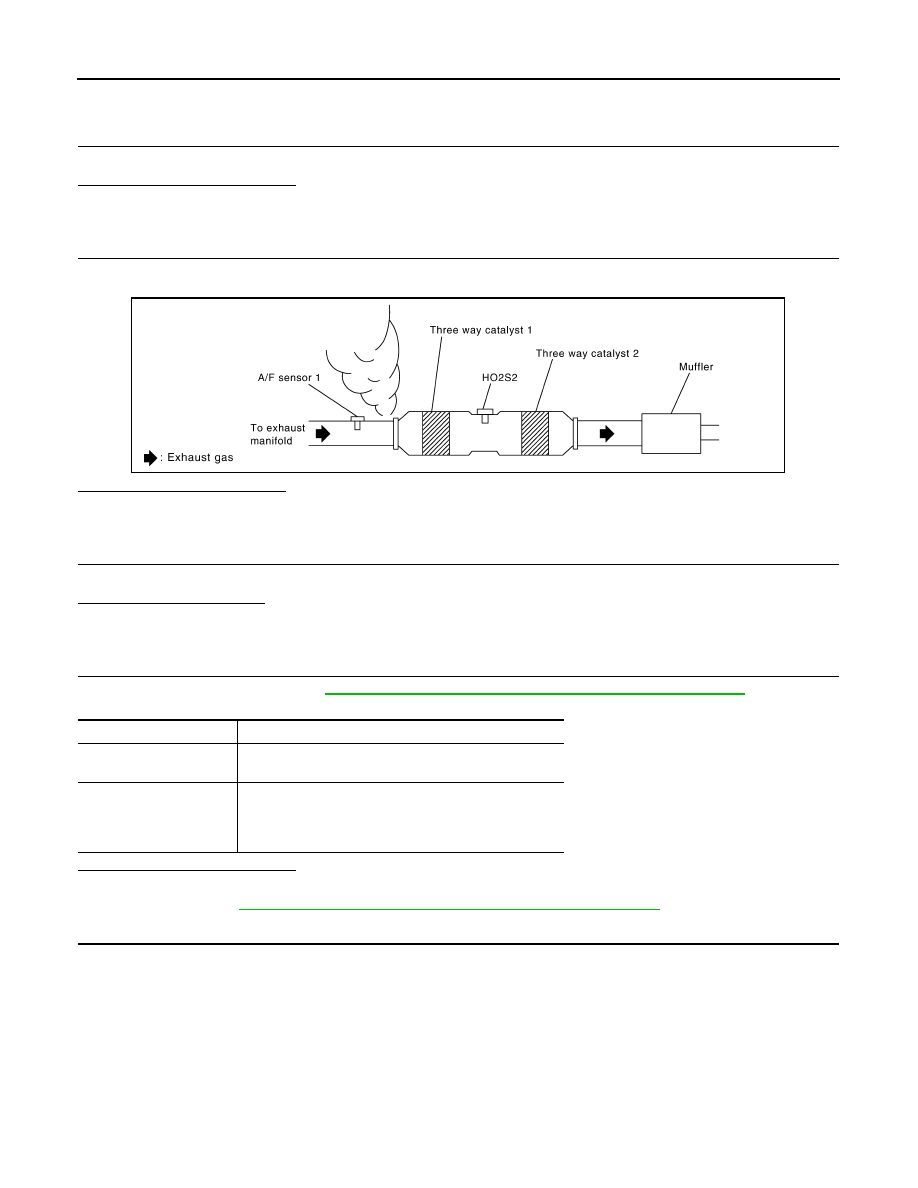
P0420, P0430 THREE WAY CATALYST FUNCTION
Diagnosis Procedure
INFOID:0000000000956652
1.
CHECK EXHAUST SYSTEM
Visually check exhaust tubes and muffler for dent.
Is the inspection result normal?
YES
>> GO TO 2.
NO
>> Repair or replace.
2.
CHECK EXHAUST GAS LEAK
1.
Start engine and run it at idle.
2.
Listen for an exhaust gas leak before the three way catalyst 1.
Is exhaust gas leak detected?
YES
>> Repair or replace.
NO
>> GO TO 3.
3.
CHECK INTAKE AIR LEAK
Listen for an intake air leak after the mass air flow sensor.
Is intake air leak detected?
YES
>> Repair or replace.
NO
>> GO TO 4.
4.
CHECK IGNITION TIMING
Check the following items. Refer to
EC-12, "BASIC INSPECTION : Special Repair Requirement"
.
Is the inspection result normal?
YES
>> GO TO 5.
NO
>> Follow the
EC-12, "BASIC INSPECTION : Special Repair Requirement"
5.
CHECK FUEL INJECTORS
1.
Stop engine and then turn ignition switch ON.
2.
Check the voltage between ECM harness connector and ground.
PBIB1922E
Items
Specifications
Target idle speed
A/T: 650
±
50 rpm (in P or N position)
M/T: 650
±
50 rpm (in Neutral position)
Ignition timing
A/T with 4WAS: 11
±
5
°
BTDC (in P or N position)
A/T without 4WAS: 15
±
5
°
BTDC (in P or N position)
M/T with 4WAS: 11
±
5
°
BTDC (in Neutral position)
M/T without 4WAS: 15
±
5
°
BTDC (in Neutral position)