Infiniti G35 (V35) Sedan. Manual - part 527


  Index      Infiniti     Infiniti G35 (V35) Sedan - service repair manual 2007 year


Search            


Content   ..  525  526  527  528   ..


Infiniti G35 (V35) Sedan. Manual - part 527


EC-254

< COMPONENT DIAGNOSIS >

[VQ35HR]

P0335 CKP SENSOR (POS)

P0335 CKP SENSOR (POS)

Description

INFOID:0000000000956642

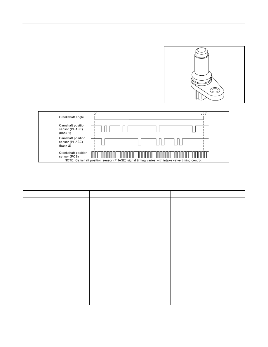
The crankshaft position sensor (POS) is located on the cylinder
block facing the gear teeth (cogs) of the signal plate. It detects the
fluctuation of the engine revolution.
The sensor consists of a permanent magnet and Hall IC.
When the engine is running, the high and low parts of the teeth
cause the gap with the sensor to change.
The changing gap causes the magnetic field near the sensor to
change.
Due to the changing magnetic field, the voltage from the sensor
changes.
The ECM receives the voltage signal and detects the fluctuation of
the engine revolution.
ECM receives the signals as shown in the figure.

DTC Logic

INFOID:0000000000956643

DTC DETECTION LOGIC

DTC CONFIRMATION PROCEDURE

1.

PRECONDITIONING

If DTC Confirmation Procedure has been previously conducted, always turn ignition switch OFF and wait at
least 10 seconds before conducting the next test.

JMBIA0062ZZ

JMBIA0001GB

DTC No.

Trouble diagnosis name

DTC detecting condition

Possible cause

P0335

Crankshaft position sen-
sor (POS) circuit

• The crankshaft position sensor (POS) signal 

is not detected by the ECM during the first 
few seconds of engine cranking.

• The proper pulse signal from the crankshaft 

position sensor (POS) is not sent to ECM 
while the engine is running.

• The crankshaft position sensor (POS) signal 

is not in the normal pattern during engine run-
ning.

• Harness or connectors

[CKP sensor (POS) circuit is open or 
shorted.]
[CMP sensor (PHASE) (bank 2) circuit is 
shorted.]
[EVT control position sensor (bank 2) cir-
cuit is shorted.]
(Battery current sensor circuit is shorted.)
(APP sensor 2 circuit is shorted.)
(EVAP control system pressure sensor 
circuit is shorted.)
(Refrigerant pressure sensor circuit is 
shorted.)

• Crankshaft position sensor (POS)
• Camshaft position sensor (PHASE) 

(bank 2)

• Exhaust valve timing control position sen-

sor (bank 2)

• Battery current sensor
• Accelerator pedal position sensor
• EVAP control system pressure sensor
• Refrigerant pressure sensor
• Signal plate

P0335 CKP SENSOR (POS)

EC-255

< COMPONENT DIAGNOSIS >

[VQ35HR]

C

D

E

F

G

H

I

J

K

L

M

A

EC

N

P

O

TESTING CONDITION:
Before performing the following procedure, confirm that battery voltage is more than 10.5V with igni-
tion switch ON.

>> GO TO 2.

2.

PERFORM DTC CONFIRMATION PROCEDURE

1.

Start engine and let it idle for at least 5 seconds.
If engine does not start, crank engine for at least 2 seconds.

2.

Check 1st trip DTC.

Is 1st trip DTC detected?

YES

>> Go to 

EC-255, "Diagnosis Procedure"

.

NO

>> INSPECTION END

Diagnosis Procedure

INFOID:0000000000956644

1.

CHECK GROUND CONNECTION

1.

Turn ignition switch OFF.

2.

Check ground connection M95. Refer to Ground Inspection in 

GI-42, "Circuit Inspection"

.

Is the inspection result normal?

YES

>> GO TO 2.

NO

>> Repair or replace ground connection.

2.

CHECK CRANKSHAFT POSITION (CKP) SENSOR (POS) POWER SUPPLY CIRCUIT-I

1.

Disconnect crankshaft position (CKP) sensor (POS) harness connector.

2.

Turn ignition switch ON.

3.

Check the voltage between CKP sensor (POS) harness connector and ground.

Is the inspection result normal?

YES

>> GO TO 8.

NO

>> GO TO 3.

3.

CHECK CRANKSHAFT POSITION (CKP) SENSOR (POS) POWER SUPPLY CIRCUIT-II

1.

Turn ignition switch ON.

2.

Disconnect ECM harness connector.

3.

Check the continuity between CKP sensor (POS) harness connector and ECM harness connector.

Is the inspection result normal?

YES

>> GO TO 4.

NO

>> Repair open circuit.

4.

CHECK CRANKSHAFT POSITION (CKP) SENSOR (POS) POWER SUPPLY CIRCUIT-III

Check harness for short to power and short to ground, between the following terminals.

CKP sensor (POS)

Ground

Voltage

Connector

Terminal

F2

1

Ground

Approx. 5V

CKP sensor (POS)

ECM

Continuity

Connector

Terminal

Connector

Terminal

F2

1

F101

46

Existed

ECM

Sensor

Connector

Terminal

Name

Connector

Terminal

F101

46

CKP sensor (POS)

F2

1

EC-256

< COMPONENT DIAGNOSIS >

[VQ35HR]

P0335 CKP SENSOR (POS)

Is the inspection result normal?

YES

>> GO TO 5.

NO

>> Repair short to ground or short to power in harness or connectors.

5.

CHECK COMPONENTS

Check the following.
• Camshaft position sensor (PHASE) (bank 2) (Refer to 

EC-262, "Component Inspection"

.)

• Exhaust valve timing control position sensor (bank 2) (Refer to 

EC-350, "Component Inspection"

.)

• Battery current sensor (Refer to 

EC-381, "Component Inspection"

.)

• EVAP control system pressure sensor (Refer to 

EC-298, "Component Inspection"

.)

• Refrigerant pressure sensor (Refer to 

HAC-92, "Component Inspection"

.)

Is the inspection result normal?

YES

>> GO TO 6.

NO

>> Replace malfunctioning component.

6.

CHECK APP SENSOR

Refer to 

EC-427, "Component Inspection"

.

Is the inspection result normal?

YES

>> GO TO 12.

NO

>> GO TO 7.

7.

REPLACE ACCELERATOR PEDAL ASSEMBLY

1.

Replace accelerator pedal assembly.

2.

Go to 

EC-427, "Special Repair Requirement"

.

>> INSPECTION END

8.

CHECK CKP SENSOR (POS) GROUND CIRCUIT FOR OPEN AND SHORT

1.

Turn ignition switch OFF.

2.

Disconnect ECM harness connector.

3.

Check the continuity between CKP sensor (POS) harness connector and ECM harness connector.

4.

Also check harness for short to ground and short to power.

Is the inspection result normal?

YES

>> GO TO 9.

NO

>> Repair open circuit or short to ground or short to power in harness or connectors.

9.

CHECK CKP SENSOR (POS) INPUT SIGNAL CIRCUIT FOR OPEN AND SHORT

1.

Check the continuity between CKP sensor (POS) harness connector and ECM harness connector.

F102

64

CMP sensor (PHASE) (bank 2)

F18

1

EVT control position sensor (bank 2)

F19

1

Battery current sensor

E21

1

M107

103

APP sensor

E112

6

107

EVAP control system pressure sensor

B252

3

111

Refrigerant pressure sensor

E77

3

ECM

Sensor

Connector

Terminal

Name

Connector

Terminal

CKP sensor (POS)

ECM

Continuity

Connector

Terminal

Connector

Terminal

F2

2

F101

47

Existed

P0335 CKP SENSOR (POS)

EC-257

< COMPONENT DIAGNOSIS >

[VQ35HR]

C

D

E

F

G

H

I

J

K

L

M

A

EC

N

P

O

2.

Also check harness for short to ground and short to power.

Is the inspection result normal?

YES

>> GO TO 10.

NO

>> Repair open circuit or short to ground or short to power in harness or connectors.

10.

CHECK CRANKSHAFT POSITION SENSOR (POS)

Refer to 

EC-257, "Component Inspection"

.

Is the inspection result normal?

YES

>> GO TO 11.

NO

>> Replace crankshaft position sensor (POS).

11.

CHECK GEAR TOOTH

Visually check for chipping signal plate gear tooth.

Is the inspection result normal?

YES

>> GO TO 12.

NO

>> Replace the signal plate.

12.

CHECK INTERMITTENT INCIDENT

Refer to 

GI-39, "Intermittent Incident"

.

>> INSPECTION END

Component Inspection

INFOID:0000000000956645

1.

CHECK CRANKSHAFT POSITION SENSOR (POS)-I

1.

Turn ignition switch OFF.

2.

Loosen the fixing bolt of the sensor.

3.

Disconnect crankshaft position sensor (POS) harness connector.

4.

Remove the sensor.

5.

Visually check the sensor for chipping.

Is the inspection result normal?

YES

>> GO TO 2.

NO

>> Replace crankshaft position sensor (POS).

2.

CHECK CRANKSHAFT POSITION SENSOR (POS)-II

Check resistance between crankshaft position sensor (POS) terminals as follows.

Is the inspection result normal?

YES

>> INSPECTION END

NO

>> Replace crankshaft position sensor (POS).

CKP sensor (POS)

ECM

Continuity

Connector

Terminal

Connector

Terminal

F2

3

F101

37

Existed

JMBIA0063ZZ

Terminals (Polarity)

Resistance

1 (+) - 2 (-)

Except 0 or 


 [at 25

°

C (77

°

F)]

1 (+) - 3 (-)

2 (+) - 3 (-)


Content   ..  525  526  527  528   ..