Infiniti G35 (V35) Sedan. Manual - part 522


  Index      Infiniti     Infiniti G35 (V35) Sedan - service repair manual 2007 year


Search            


Content   ..  520  521  522  523   ..


Infiniti G35 (V35) Sedan. Manual - part 522


EC-234

< COMPONENT DIAGNOSIS >

[VQ35HR]

P0182, P0183 FTT SENSOR

Is the inspection result normal?

YES

>> GO TO 3.

NO

>> Go to 

MWI-53, "Component Function Check"

.

3.

CHECK FUEL TANK TEMPERATURE SENSOR POWER SUPPLY CIRCUIT

1.

Turn ignition switch OFF.

2.

Disconnect “fuel level sensor unit and fuel pump” harness connector.

3.

Turn ignition switch ON.

4.

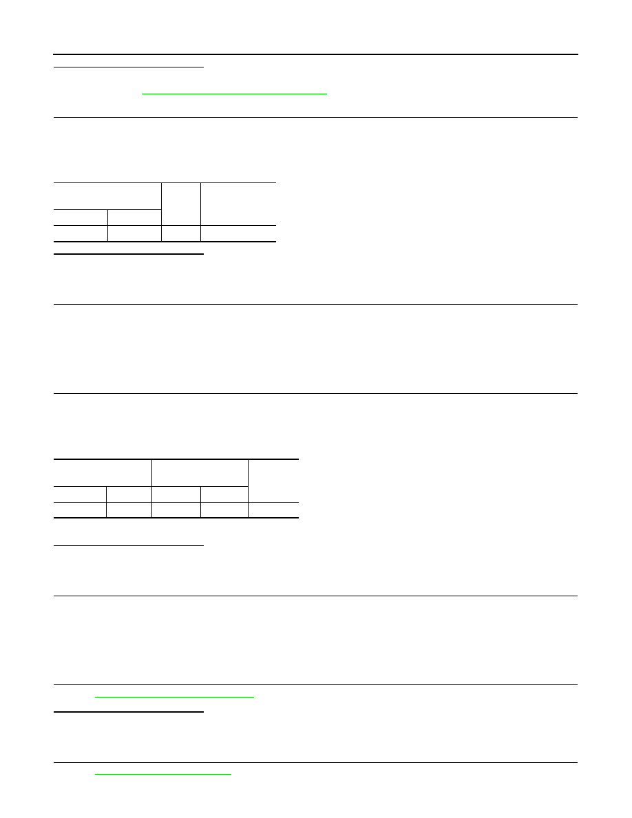
Check the voltage between “fuel level sensor unit and fuel pump” harness connector and ground.

Is the inspection result normal?

YES

>> GO TO 5.

NO

>> GO TO 4.

4.

DETECT MALFUNCTIONING PART

Check the following.
• Harness connectors M7, B1
• Harness for open or short between ECM and “fuel level sensor unit and fuel pump”

>> Repair open circuit or short to ground or short to power in harness or connector.

5.

CHECK FUEL TANK TEMPERATURE SENSOR GROUND CIRCUIT FOR OPEN AND SHORT

1.

Turn ignition switch OFF.

2.

Disconnect “unified meter and A/C amp.” harness connector.

3.

Check the continuity between “fuel level sensor unit and fuel pump” harness connector and “unified meter
and A/C amp.” harness connector.

4.

Also check harness for short to ground and short to power.

Is the inspection result normal?

YES

>> GO TO 7.

NO

>> GO TO 6.

6.

DETECT MALFUNCTIONING PART

Check the following.
• Harness connectors M7, B1
• Harness for open or short between “fuel level sensor unit and fuel pump” and “unified meter and A/C amp.”

>> Repair open circuit or short to ground or short to power in harness or connector.

7.

CHECK FUEL TANK TEMPERATURE SENSOR

Refer to 

EC-235, "Component Inspection"

.

Is the inspection result normal?

YES

>> GO TO 8.

NO

>> Replace “fuel level sensor unit and fuel pump”.

8.

CHECK INTERMITTENT INCIDENT

Refer to 

GI-39, "Intermittent Incident"

.

Fuel level sensor unit and 

fuel pump

Ground

Voltage

Connector

Terminal

B22

4

Ground

Approx. 5V

Fuel level sensor unit 

and fuel pump

Unified meter and A/C 

amp.

Continuity

Connector

Terminal

Connector

Terminal

B22

5

M67

58

Existed

P0182, P0183 FTT SENSOR

EC-235

< COMPONENT DIAGNOSIS >

[VQ35HR]

C

D

E

F

G

H

I

J

K

L

M

A

EC

N

P

O

>> INSPECTION END

Component Inspection

INFOID:0000000000956622

1.

CHECK FUEL TANK TEMPERATURE SENSOR

1.

Turn ignition switch OFF.

2.

Disconnect “fuel level sensor unit and fuel pump” harness connector.

3.

Remove fuel level sensor unit.

4.

Check resistance between “fuel level sensor unit and fuel pump”
terminals by heating with hot water as shown in the figure.

Is the inspection result normal?

YES

>> INSPECTION END

NO

>> Replace “fuel level sensor unit and fuel pump”.

Terminals

Condition

Resistance

4 and 5

Temperature

°

C (

°

F)

20 (68)

2.3 - 2.7

k

50 (122)

0.79 - 0.90

k

JMBIA0167ZZ

EC-236

< COMPONENT DIAGNOSIS >

[VQ35HR]

P0196 EOT SENSOR

P0196 EOT SENSOR

Description

INFOID:0000000000956623

The engine oil temperature sensor is used to detect the engine oil
temperature. The sensor modifies a voltage signal from the ECM.
The modified signal returns to the ECM as the engine oil tempera-
ture input. The sensor uses a thermistor which is sensitive to the
change in temperature. The electrical resistance of the thermistor
decreases as temperature increases.

<Reference data>

*: These data are reference values and are measured between ECM terminal 78
(Engine oil temperature sensor) and ground.

CAUTION:

Do not use ECM ground terminals when measuring input/output voltage. Doing so may result in damage to the ECM’s transis-
tor. Use a ground other than ECM terminals, such as the ground.

DTC Logic

INFOID:0000000000956624

DTC DETECTION LOGIC

NOTE:
If DTC P0196 is displayed with P0197 or P0198, first perform the trouble diagnosis for DTC P0197 or
P0198. Refer to 

EC-239, "DTC Logic"

.

DTC CONFIRMATION PROCEDURE

1.

PRECONDITIONING

If DTC Confirmation Procedure has been previously conducted, always turn ignition switch OFF and wait at
least 10 seconds before conducting the next test.
TESTING CONDITION:
Before performing the following procedure, confirm that battery voltage is more than 11V at idle.

>> GO TO 2.

2.

PERFORM DTC CONFIRMATION PROCEDURE-I

1.

Start engine and warm it up to normal operating temperature.

SEF594K

Engine oil temperature

°

C (

°

F)

Voltage*

V

Resistance

k

–10 (14)

4.4

7.0 - 11.4

20 (68)

3.5

2.1 - 2.9

50 (122)

2.2

0.68 - 1.00

90 (194)

0.9

0.236 - 0.260

110 (230)

0.6

0.143 - 0.153

SEF012P

DTC No.

Trouble diagnosis name

DTC detecting condition

Possible cause

P0196

Engine oil temperature 
sensor range/perfor-
mance

Rationally incorrect voltage from the sensor is 
sent to ECM, compared with the voltage signals 
from engine coolant temperature sensor and in-
take air temperature sensor.

• Harness or connectors

(The sensor circuit is open or shorted)

• Engine oil temperature sensor

P0196 EOT SENSOR

EC-237

< COMPONENT DIAGNOSIS >

[VQ35HR]

C

D

E

F

G

H

I

J

K

L

M

A

EC

N

P

O

2.

Turn ignition switch OFF and wait at least 10 seconds.

3.

Start engine and let it idle for 5 minutes and 10 seconds.

4.

Check 1st trip DTC.

Is 1st trip DTC detected?

YES

>>

EC-237, "Diagnosis Procedure"

.

NO

>> GO TO 3.

3.

PERFORM DTC CONFIRMATION PROCEDURE-II

 With CONSULT-III

1.

Select “DATA MONITOR” mode with CONSULT-III.

2.

Check that “COOLAN TEMP/S” indicates above 80

°

C (176

°

F).

If it is above 80

°

C (176

°

F), go to the following steps.

If it is below 80

°

C (176

°

F), warm engine up until “COOLAN TEMP/S” indicates more than 80

°

C (176

°

F).

Then go to the following steps.

3.

Turn ignition switch OFF and soak the vehicle at cool place.

4.

Turn ignition switch ON.
NOTE:
Do not turn ignition switch OFF until step 8.

5.

Select “DATA MONITOR” mode with CONSULT-III.

6.

Check the following.

If they are within the specified range, go to following steps.
If they are out of the specified range, soak the vehicle to meet the above conditions. Then go to following
steps.
NOTE:
• Do not turn ignition switch OFF.
• If it is supposed to need a long period of time, do not deplete the battery.

7.

Start engine and let it idle for 5 minutes.

8.

Check 1st trip DTC.

 With GST

Follow the procedure “With CONSULT-III” above.
Is 1st trip DTC detected?

YES

>>

EC-237, "Diagnosis Procedure"

.

NO

>> INSPECTION END

Diagnosis Procedure

INFOID:0000000000956625

1.

CHECK GROUND CONNECTION

1.

Turn ignition switch OFF.

2.

Check ground connection M95. Refer to Ground Inspection in 

GI-42, "Circuit Inspection"

.

Is the inspection result normal?

YES

>> GO TO 2.

NO

>> Repair or replace ground connection.

2.

CHECK ENGINE OIL TEMPERATURE SENSOR

Refer to 

EC-238, "Component Inspection"

.

Is the inspection result normal?

YES

>> GO TO 3.

NO

>> Replace engine oil temperature sensor.

3.

CHECK INTERMITTENT INCIDENT

Refer to 

GI-39, "Intermittent Incident"

.

COOLAN TEMP/S

Below 40

°

C (104

°

F)

INT/A TEMP SE

Below 40

°

C (104

°

F)

Difference between “COOLAN TEMP/S” and “INT/A TEMP SE”

Within 6

°

C (11

°

F)


Content   ..  520  521  522  523   ..