Infiniti G35 (V35) Sedan. Manual - part 515


  Index      Infiniti     Infiniti G35 (V35) Sedan - service repair manual 2007 year


Search            


Content   ..  513  514  515  516   ..


Infiniti G35 (V35) Sedan. Manual - part 515


EC-206

< COMPONENT DIAGNOSIS >

[VQ35HR]

P0137, P0157 HO2S2

6.

Select “FUEL INJECTION” in “ACTIVE TEST” mode, and select “HO2S2 (B1)/(B2)” as the monitor item
with CONSULT-III.

7.

Check “HO2S2 (B1)/(B2)” at idle speed when adjusting “FUEL INJECTION” to 

±

25%.

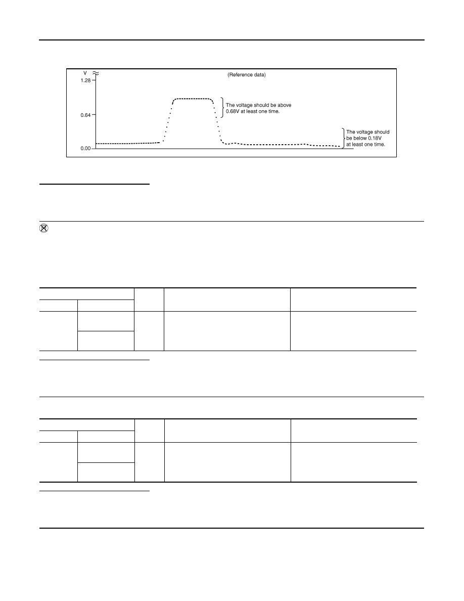
“HO2S2 (B1)/(B2)” should be above 0.68V at least once when the “FUEL INJECTION” is +25%.
“HO2S2 (B1)/(B2)” should be below 0.18V at least once when the “FUEL INJECTION” is 

25%.

Is the inspection result normal?

YES

>> INSPECTION END

NO

>> GO TO 6.

3.

CHECK HEATED OXYGEN SENSOR 2-I

 Without CONSULT-III

1.

Start engine and warm it up to the normal operating temperature.

2.

Turn ignition switch OFF and wait at least 10 seconds.

3.

Start engine and keep the engine speed between 3,500 and 4,000 rpm for at least 1 minute under no load.

4.

Let engine idle for 1 minute.

5.

Check the voltage between ECM harness connector and ground under the following condition.

Is the inspection result normal?

YES

>> INSPECTION END

NO

>> GO TO 4.

4.

CHECK HEATED OXYGEN SENSOR 2-II

Check the voltage between ECM harness connector and ground under the following condition.

Is the inspection result normal?

YES

>> INSPECTION END

NO

>> GO TO 5.

5.

CHECK HEATED OXYGEN SENSOR 2-III

Check the voltage between ECM harness connector and ground under the following condition.

PBIB3458E

ECM

Ground

Condition

Voltage

Connector

Terminal

F102

76

[HO2S2 (bank 1)]

Ground

Revving up to 4,000 rpm under no load at 
least 10 times

The voltage should be above 0.68V at 
least once during this procedure.
The voltage should be below 0.18V at least 
once during this procedure.

80

[HO2S2 (bank 2)]

ECM

Ground

Condition

Voltage

Connector

Terminal

F102

76

[HO2S2 (bank 1)]

Ground

Keeping engine at idle for 10 minutes

The voltage should be above 0.68V at 
least once during this procedure.
The voltage should be below 0.18V at least 
once during this procedure.

80

[HO2S2 (bank 2)]

P0137, P0157 HO2S2

EC-207

< COMPONENT DIAGNOSIS >

[VQ35HR]

C

D

E

F

G

H

I

J

K

L

M

A

EC

N

P

O

Is the inspection result normal?

YES

>> INSPECTION END

NO

>> GO TO 6.

6.

REPLACE HEATED OXYGEN SENSOR 2

Replace malfunctioning heated oxygen sensor 2.

CAUTION:

• Discard any heated oxygen sensor which has been dropped from a height of more than 0.5 m (19.7

in) onto a hard surface such as a concrete floor; use a new one.

• Before installing new oxygen sensor, clean exhaust system threads using Oxygen Sensor Thread

Cleaner tool J-43897-18 or J-43897-12 and approved anti-seize lubricant.

>> INSPECTION END

ECM

Ground

Condition

Voltage

Connector

Terminal

F102

76

[HO2S2 (bank 1)]

Ground

Coasting from 80 km/h (50 MPH) in D po-
sition (A/T), 4th gear position (M/T)

The voltage should be above 0.68V at 
least once during this procedure.
The voltage should be below 0.18V at least 
once during this procedure.

80

[HO2S2 (bank 2)]

EC-208

< COMPONENT DIAGNOSIS >

[VQ35HR]

P0138, P0158 HO2S2

P0138, P0158 HO2S2

Description

INFOID:0000000000956601

The heated oxygen sensor 2, after three way catalyst 1, monitors the
oxygen level in the exhaust gas on each bank.
Even if switching characteristics of the air fuel ratio (A/F) sensor 1
are shifted, the air-fuel ratio is controlled to stoichiometric, by the sig-
nal from the heated oxygen sensor 2.
This sensor is made of ceramic zirconia. The zirconia generates volt-
age from approximately 1V in richer conditions to 0V in leaner condi-
tions.
Under normal conditions the heated oxygen sensor 2 is not used for
engine control operation.

DTC Logic

INFOID:0000000000956602

DTC DETECTION LOGIC

The heated oxygen sensor 2 has a much longer switching time between rich and lean than the air fuel ratio (A/
F) sensor 1. The oxygen storage capacity of the three way catalyst 1 causes the longer switching time.
MALFUNCTION A
To judge the malfunctions of heated oxygen sensor 2, ECM monitors
whether the voltage is unusually high during the various driving con-
dition such as fuel-cut.

MALFUNCTION B
To judge the malfunctions of heated oxygen sensor 2, ECM monitors
whether the minimum voltage of sensor is sufficiently low during the
various driving condition such as fuel-cut.

SEF327R

PBIB1848E

PBIB2376E

DTC No.

Trouble diagnosis name

DTC detecting condition

Possible cause

P0138

Heated oxygen sensor 2 
(bank 1) circuit high volt-
age

A)

An excessively high voltage from the sen-
sor is sent to ECM.

• Harness or connectors

(The sensor circuit is open or shorted)

• Heated oxygen sensor 2

B)

The minimum voltage from the sensor is 
not reached to the specified voltage.

• Harness or connectors

(The sensor circuit is open or shorted)

• Heated oxygen sensor 2
• Fuel pressure
• Fuel injector

P0138, P0158 HO2S2

EC-209

< COMPONENT DIAGNOSIS >

[VQ35HR]

C

D

E

F

G

H

I

J

K

L

M

A

EC

N

P

O

DTC CONFIRMATION PROCEDURE

1.

PRECONDITIONING

If DTC Confirmation Procedure has been previously conducted, always turn ignition switch OFF and wait at
least 10 seconds before conducting the next test.

>> GO TO 2.

2.

PERFORM DTC CONFIRMATION PROCEDURE FOR MALFUNCTION A

1.

Start engine and warm it up to the normal operating temperature.

2.

Turn ignition switch OFF and wait at least 10 seconds.

3.

Start engine and keep the engine speed between 3,500 and 4,000 rpm for at least 1 minute under no load.

4.

Check 1st trip DTC.

Is 1st trip DTC detected?

YES

>> Go to 

EC-210, "Diagnosis Procedure"

.

NO-1

>> With CONSULT-III: GO TO 3.

NO-2

>> Without CONSULT-III: GO TO 5.

3.

PERFORM DTC CONFIRMATION PROCEDURE FOR MALFUNCTION B

NOTE:
For better results, perform “DTC WORK SUPPORT” at a temperature of 0 to 30 

°

C (32 to 86 

°

F).

1.

Select “DATA MONITOR” mode with CONSULT-III.

2.

Start engine and warm it up to the normal operating temperature.

3.

Turn ignition switch OFF and wait at least 10 seconds.

4.

Start engine and keep the engine speed between 3,500 and 4,000 rpm for at least 1 minute under no load.

5.

Let engine idle for 1 minute.

6.

Make sure that “COOLAN TEMP/S” indicates more than 70

°

C (158

°

F).

If not, warm up engine and go to next step when “COOLAN TEMP/S” indication reaches to 70

°

C (158

°

F).

7.

Open engine hood.

8.

Select “HO2S2 (B1) P1146” (for DTC P0138) or “HO2S2 (B2) P1166” (for DTC P0158) of “HO2S2” in
“DTC WORK SUPPORT” mode with CONSULT-III.

9.

Start engine and following the instruction of CONSULT-III.
NOTE:
It will take at most 10 minutes until “COMPLETED” is displayed.

10. Touch “SELF-DIAG RESULTS”.

Which is displayed on CONSULT-III screen?

OK

>> INSPECTION END

NG

>> Go to 

EC-210, "Diagnosis Procedure"

.

CON NOT BE DIAGNOSED>>GO TO 4.

4.

PERFORM DTC CONFIRMATION PROCEDURE FOR MALFUNCTION B AGAIN

1.

Turn ignition switch OFF and leave the vehicle in a cool place (soak the vehicle).

2.

Perform DTC confirmation procedure again.

>> GO TO 3.

5.

PERFORM COMPONENT FUNCTION CHECK FOR MALFUNCTION B

Perform component function check. Refer to 

EC-210, "Component Function Check"

.

NOTE:

P0158

Heated oxygen sensor 2 
(bank 2) circuit high volt-
age

A)

An excessively high voltage from the sen-
sor is sent to ECM.

• Harness or connectors

(The sensor circuit is open or shorted)

• Heated oxygen sensor 2

B)

The minimum voltage from the sensor is 
not reached to the specified voltage.

• Harness or connectors

(The sensor circuit is open or shorted)

• Heated oxygen sensor 2
• Fuel pressure
• Fuel injector

DTC No.

Trouble diagnosis name

DTC detecting condition

Possible cause


Content   ..  513  514  515  516   ..