Infiniti G35 (V35) Sedan. Manual - part 475
EC-46
< FUNCTION DIAGNOSIS >
[VQ35HR]
ELECTRIC IGNITION SYSTEM
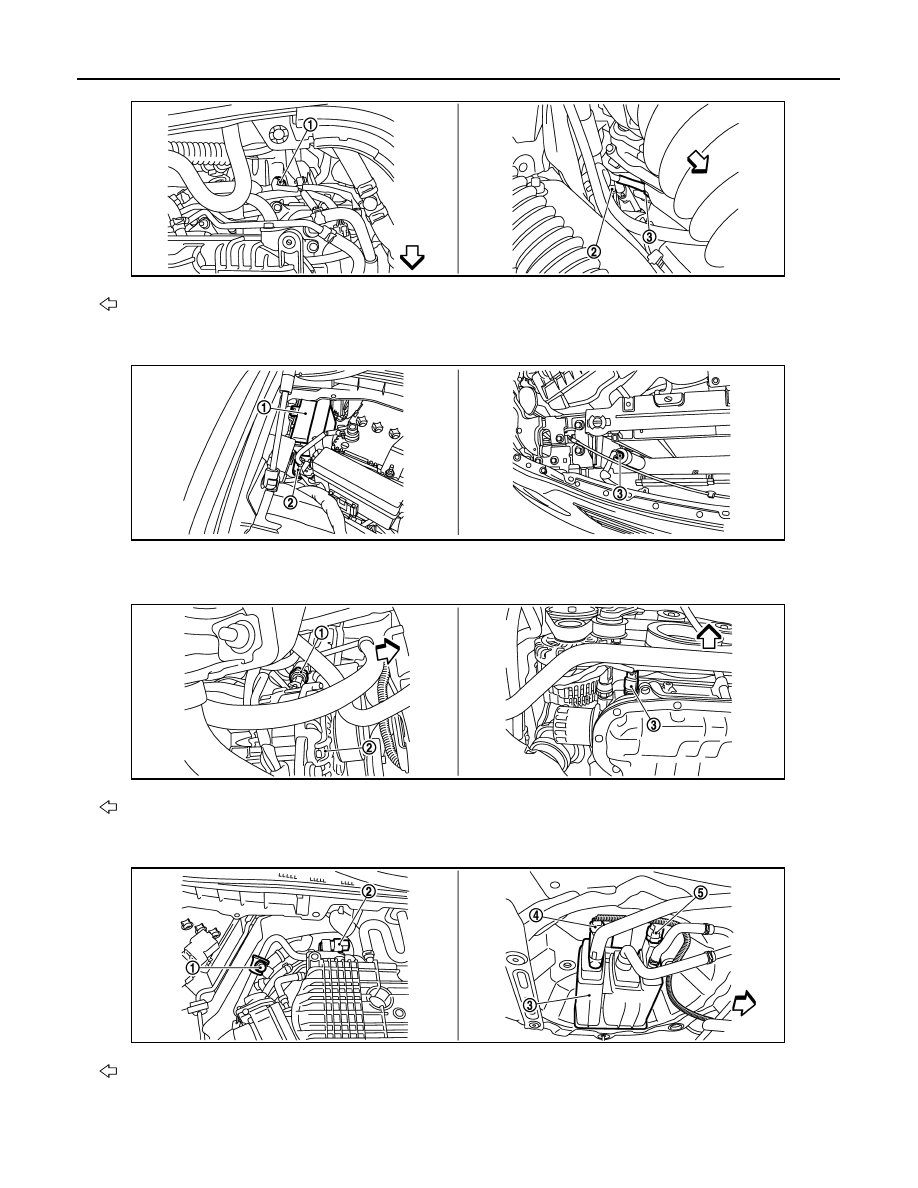
: Vehicle front
1.
Engine coolant temperature sensor
2.
A/F sensor 1 (bank 1)
3.
Crankshaft position sensor (POS)
1.
IPDM E/R
2.
Battery current sensor
3.
Refrigerant pressure sensor
: Vehicle front
1.
Power steering pressure sensor
2.
Alternator
3.
Engine oil temperature sensor
: Vehicle front
JMBIA0011ZZ
JMBIA0013ZZ
JMBIA0014ZZ
JMBIA0012ZZ