Infiniti G35 (V35) Sedan. Manual - part 469
EC-22
< FUNCTION DIAGNOSIS >
[VQ35HR]
ENGINE CONTROL SYSTEM
FUNCTION DIAGNOSIS
ENGINE CONTROL SYSTEM
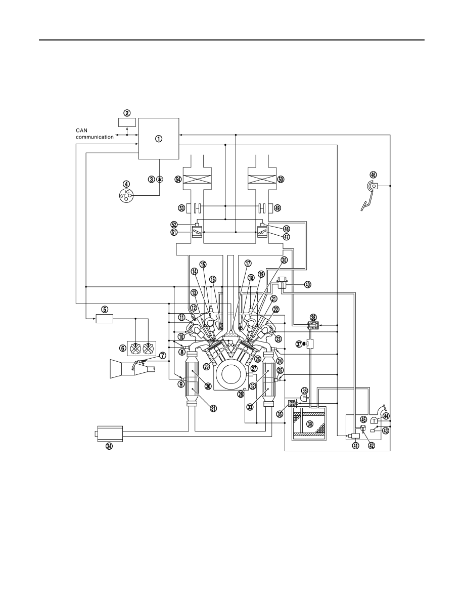
System Diagram
INFOID:0000000000956478
1.
ECM
2.
Data link connector
3.
MIL
4.
Ignition switch
5.
Cooling fan control module
6.
Cooling fan
7.
PNP switch
8.
A/F sensor 1
9.
Heated oxygen sensor 2
10. Exhaust valve timing control magnet
retarder
11.
Exhaust valve timing control position
sensor
12. PCV valve
13. Spark plug
14. Camshaft position sensor (PHASE)
15. Intake valve timing control solenoid
valve
16. Fuel injector
17. Engine coolant temperature sensor
18. Fuel injector
19. Intake valve timing control solenoid
valve
20. Camshaft position sensor (PHASE)
21. Spark plug
JMBIA0050GB