Infiniti G35 (V35) Sedan. Manual - part 360


  Index      Infiniti     Infiniti G35 (V35) Sedan - service repair manual 2007 year


Search            


Content   ..  358  359  360  361   ..


Infiniti G35 (V35) Sedan. Manual - part 360


OUTSIDE KEY ANTENNA

DLK-101

< COMPONENT DIAGNOSIS >

[INTELLIGENT KEY SYSTEM]

C

D

E

F

G

H

I

J

L

M

A

B

DLK

N

O

P

OUTSIDE KEY ANTENNA

Description

INFOID:0000000000961203

Detects whether Intelligent Key is outside the vehicle.
Integrated in front outside handle (driver side, passenger side) and installed in rear bumper.

Component Function Check

INFOID:0000000000961204

1.

CHECK DOOR REQUEST SWITCH

Check that door request switch operates normally.

Is the inspection result normal?

YES

>> GO TO 2.

NO

>> Inspect door request switch. Refer to 

DLK-87, "Component Function Check"

.

2.

CHECK FUNCTION

Be sure that Intelligent Key is in each outside key antenna detection range.

Does door lock/unlock when each request switch is pressed?

YES

>> Outside key antenna is OK.

NO

>> Refer to 

DLK-101, "Diagnosis Procedure"

.

Diagnosis Procedure

INFOID:0000000000961205

1.

CHECK OUTSIDE KEY ANTENNA INPUT SIGNAL 1

1.

Turn ignition switch OFF.

2.

Check signal between BCM connector and ground with oscilloscope.

Is the inspection result normal? 

YES

>> GO TO 4.

NO

>> GO TO 2.

2.

CHECK OUTSIDE KEY ANTENNA CIRCUIT

1.

Disconnect BCM and front outside handle connector.

2.

Check continuity between BCM connector and outside key antenna connector.
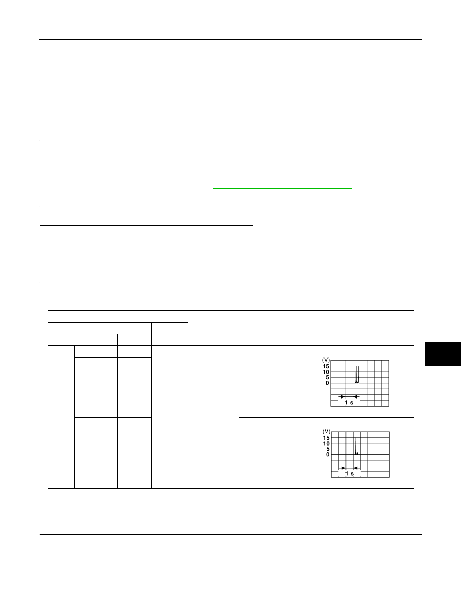
Terminals

Condition

Signal

(Reference value.)

(+)

(–)

BCM connector

Terminal

M122

Driver side

77

Ground

Request switch 

is pushed

When Intelligent Key 
is in the antenna de-
tection area.

Passenger 

side

75

Rear 

bumper

39

When Intelligent Key 
is not in the antenna 
detection area.

JMKIA0061GB

JMKIA0060GB

DLK-102

< COMPONENT DIAGNOSIS >

[INTELLIGENT KEY SYSTEM]

OUTSIDE KEY ANTENNA

3.

Check continuity between BCM connector and ground.

Is the inspection result normal?

YES

>> GO TO 3.

NO

>> Repair or replace harness between BCM and outside key antenna.

3.

CHECK OUTSIDE KEY ANTENNA INPUT SIGNAL 2

1.

Replace outside key antenna. (New antenna or other antenna)

2.

Connect BCM and outside key antenna connector.

3.

Check signal between BCM connector and ground with oscilloscope.

Is the inspection result normal?

YES

>> Replace outside key antenna. Refer to 

DLK-201, "FRONT DOOR : Removal and Installation"

(Driver side and passenger side), 

DLK-221, "REAR BUMPER : Removal and Installation"

 (Rear

bumper)

NO

>> GO TO 4.

4.

CHECK INTERMITTENT INCIDENT

Refer to 

GI-39, "Intermittent Incident"

.

BCM connector

Terminal

 Outside key antenna connector

Terminal

Continuity 

M122

77

D14 (driver side)

1

Existed

76

2

75

D44 (passenger side)

1

74

2

M121

39

B63 (rear bumper)

1

38

2

BCM connector

Terminal

Ground

Continuity 

M122

74

Not existed

75

76

77

M121

39

38

Terminals

Condition

Signal

(Reference value.)

(+)

(–)

BCM connector

Terminal

M122

Driver side

77

Ground

Door request 

switch is 

pushed

When Intelligent Key 
is in the antenna de-
tection area.

Passenger 

side

75

Rear bumper

39

When Intelligent Key 
is not in the antenna 
detection area.

JMKIA0061GB

JMKIA0060GB

OUTSIDE KEY ANTENNA

DLK-103

< COMPONENT DIAGNOSIS >

[INTELLIGENT KEY SYSTEM]

C

D

E

F

G

H

I

J

L

M

A

B

DLK

N

O

P

>> INSPECTION END.

DLK-104

< COMPONENT DIAGNOSIS >

[INTELLIGENT KEY SYSTEM]

REMOTE KEYLESS ENTRY RECEIVER

REMOTE KEYLESS ENTRY RECEIVER

Description

INFOID:0000000000961206

Receives Intelligent Key operation and transmits to BCM.

Component Function Check

INFOID:0000000000961207

1.

CHECK FUNCTION

 With CONSULT-III

Check remote keyless entry receiver (“RKE OPE COUN1”) in Data Monitor mode with CONSULT-III.

Is the inspection result normal?

YES

>> Remote keyless entry receiver is OK.

NO

>> Refer to 

DLK-104, "Diagnosis Procedure"

.

Diagnosis Procedure

INFOID:0000000000961208

1.

CHECK REMOTE KEYLESS ENTRY RECEIVER OUTPUT SIGNAL

1.

Turn ignition switch OFF.

2.

Check signal between remote keyless entry receiver connector and ground with oscilloscope.

Is the inspection result normal?

YES

>> GO TO 7.

NO

>> GO TO 2.

2.

CHECK REMOTE KEYLESS ENTRY RECEIVER POWER SUPPLY 

1.

Disconnect remote keyless entry receiver connector.

2.

Check signal between remote keyless entry receiver connector and ground with oscilloscope.

Monitor item

Condition

RKE OPE COUN1

Checks whether value changes when operating Intelligent Key.

Terminals

Condition

Signal

(Reference value)

(+)

(–)

Remote keyless 

entry receiver 

connector

Terminal

M104

2

Ground

Waiting

(All door closed)

When signal is received

(All door closed)

JMKIA0064GB

JMKIA0065GB


Content   ..  358  359  360  361   ..