Infiniti G35 (V35) Sedan. Manual - part 319
CO-24
< ON-VEHICLE REPAIR >
WATER OUTLET AND WATER PIPING
WATER OUTLET AND WATER PIPING
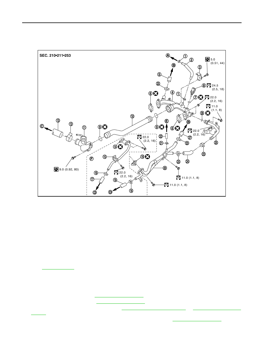
Exploded View
INFOID:0000000000956358
Removal and Installation
INFOID:0000000000956359
REMOVAL
1.
Remove engine cover. Refer to
2.
Remove reservoir tank. Refer to
.
3.
Remove oil level gauge and guide. Refer to
.
4.
Remove air duct and air cleaner case assembly (RH and LH). Refer to
5.
Remove engine undercover with power tool.
1.
Clamp
2.
Water hose
3.
Harness bracket
4.
Water outlet (rear)
5.
Heater hose
6.
Gasket
7.
Washer
8.
Engine coolant temperature sensor
9.
O-ring
10. Water outlet pipe
11.
Water outlet (front)
12.
Clamp
13. Radiator hose (upper)
14.
Gasket
15.
Water pipe
16. Clamp
17.
Water hose
18.
Water hose
19. Gasket
20.
Heater pipe
21.
Clamp
22. Water hose
23.
Clamp
24.
Heater hose
25. Water bypass pipe
26.
O-ring
27.
Heater hose
A.
To EVAP piping
B.
To heater core
C.
To radiator
D.
To oil cooler
E.
To electric throttle control actuator
F.
AWD models
Refer to
for symbol marks in the figure.
JPBIA0247GB