Infiniti G35 (V35) Sedan. Manual - part 218
BRAKE PEDAL
BR-9
< ON-VEHICLE MAINTENANCE >
C
D
E
G
H
I
J
K
L
M
A
B
BR
N
O
P
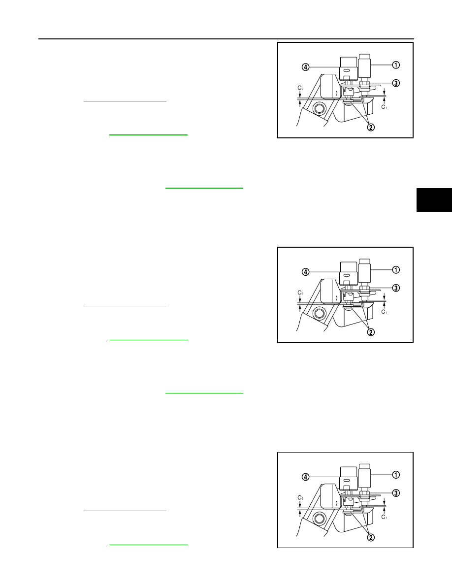
4.
Press the brake pedal pad slightly. Release the brake pedal.
Turn ASCD cancel switch (1) until ASCD cancel switch threaded
end hits to the stopper rubber (2) clockwise.
CAUTION:
Never press-fit the input rod.
5.
Tighten ASCD cancel switch lock nut (3) to the specification.
Refer to
.
CAUTION:
The clearance (C
1
) between the stopper rubber and the
ASCD cancel switch threaded end must be the specified
value. Refer to
.
6.
Press-fit the stop lamp switch (4) until the stop lamp switch hits
the stopper rubber 45
°
clockwise while pulling the brake pedal pad slightly. (ASCD cancel switch threaded
end hits the stopper rubber.)
CAUTION:
• The clearance (C
2
) between the stopper rubber and the stop lamp switch threaded end must be
the specified value. Refer to
.
• The stop lamp must turn off when the brake pedal is released.
Brake Pedal Play
1.
Disconnect the harness connector from ASCD cancel switch and stop lamp switch.
2.
Turn the stop lamp switch 45
°
counterclockwise.
3.
Loosen ASCD cancel switch lock nut. Turn ASCD cancel switch counterclockwise.
4.
Press the brake pedal pad slightly. Release the brake pedal.
Turn ASCD cancel switch (1) until ASCD cancel switch threaded
end hits to the stopper rubber (2) clockwise.
CAUTION:
Never press-fit the input rod.
5.
Tighten ASCD cancel switch lock nut (3) to the specification.
Refer to
.
CAUTION:
The clearance (C
1
) between the stopper rubber and the
ASCD cancel switch threaded end must be the specified
value. Refer to
.
6.
Press-fit the stop lamp switch (4) until the stop lamp switch hits
the stopper rubber 45
°
clockwise while pulling the brake pedal pad slightly. (ASCD cancel switch threaded
end hits the stopper rubber.)
CAUTION:
• The clearance (C
2
) between the stopper rubber and the stop lamp switch threaded end must be
the specified value. Refer to
.
• The stop lamp must turn off when the brake pedal is released.
Brake Pedal Shaky Fitting
1.
Disconnect the harness connector from ASCD cancel switch and stop lamp switch.
2.
Turn the stop lamp switch 45
°
counterclockwise.
3.
Loosen ASCD cancel switch lock nut. Turn ASCD cancel switch counterclockwise.
4.
Press the brake pedal pad slightly. Release the brake pedal.
Turn ASCD cancel switch (1) until ASCD cancel switch threaded
end hits to the stopper rubber (2) clockwise.
CAUTION:
Never press-fit the input rod.
5.
Tighten ASCD cancel switch lock nut (3) to the specification.
Refer to
.
CAUTION:
The clearance (C
1
) between the stopper rubber and the
ASCD cancel switch threaded end must be the specified
value. Refer to
.
JPFIA0071ZZ
JPFIA0071ZZ
JPFIA0071ZZ