Infiniti G35 (V35) Sedan. Manual - part 215
BCS
COMBINATION SWITCH SYSTEM SYMPTOMS
BCS-77
< SYMPTOM DIAGNOSIS >
C
D
E
F
G
H
I
J
K
L
B
A
O
P
N
SYMPTOM DIAGNOSIS
COMBINATION SWITCH SYSTEM SYMPTOMS
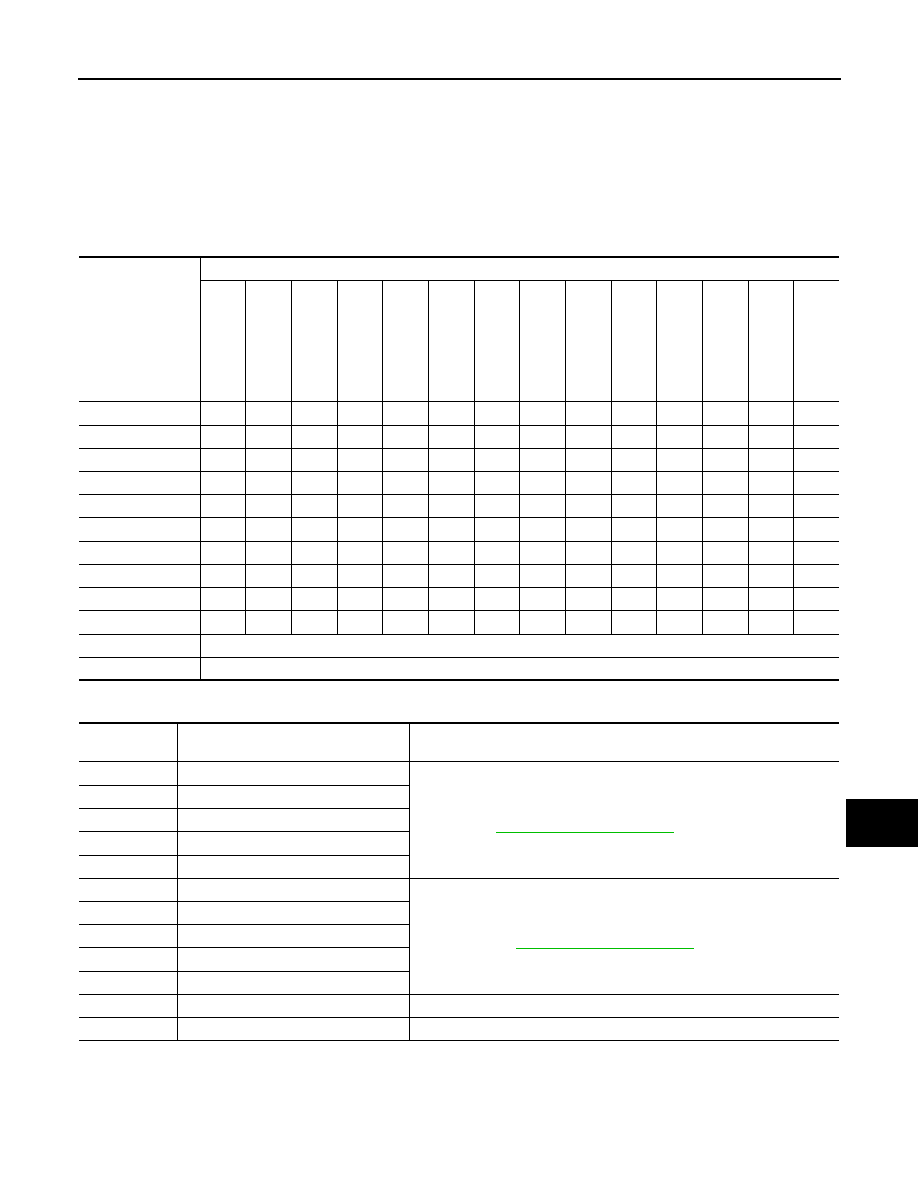
Symptom Table
INFOID:0000000000963915
1.
Perform “Data Monitor” of CONSULT-III to check for any malfunctioning item.
2.
Check the malfunction combinations.
Malfunction item:
×
3.
Identify the malfunctioning part from the agreed combination and repair or replace the part.
Malfunction combi-
nation
Data monitor item
FR WI
PER HI
FR WIP
E
R LOW
F
R
W
A
SH
ER
S
W
FR WI
PER INT
INT VOL
U
ME
TURN SIG
N
AL R
TURN SIGNAL L
T
A
IL
LA
MP
SW
H
I BEAM SW
HEAD LAMP SW
1
HEAD LAMP SW
2
P
ASSI
N
G
SW
AU
T
O
LI
GH
T
S
W
FR F
O
G
SW
A
×
×
×
×
B
×
×
×
×
C
×
×
×
D
×
×
×
E
×
×
F
×
×
G
×
×
H
×
×
×
I
×
×
×
×
J
×
×
×
×
K
All Items
L
If only one item is detected or the item is not applicable to the combinations A to K
Malfunction
combination
Malfunctioning part
Repair or replace
A
Combination switch INPUT 1 circuit
Inspect the combination switch input circuit applicable to the malfunctioning
part. Refer to
.
B
Combination switch INPUT 2 circuit
C
Combination switch INPUT 3 circuit
D
Combination switch INPUT 4 circuit
E
Combination switch INPUT 5 circuit
F
Combination switch OUTPUT 1 circuit
Inspect the combination switch output circuit applicable to the malfunction-
ing part. Refer to
.
G
Combination switch OUTPUT 2 circuit
H
Combination switch OUTPUT 3 circuit
I
Combination switch OUTPUT 4 circuit
J
Combination switch OUTPUT 5 circuit
K
BCM
Replace BCM.
L
Combination switch
Replace the combination switch.