Infiniti G35 (V35) Sedan. Manual - part 206
BCS
COMBINATION SWITCH OUTPUT CIRCUIT
BCS-41
< COMPONENT DIAGNOSIS >
C
D
E
F
G
H
I
J
K
L
B
A
O
P
N
COMBINATION SWITCH OUTPUT CIRCUIT
Diagnosis Procedure
INFOID:0000000000963908
1.
CHECK OUTPUT 1 - 5 SYSTEM CIRCUIT FOR OPEN
1.
Turn the ignition switch OFF.
2.
Disconnect the BCM and combination switch connectors.
3.
Check continuity between BCM harness connector and combination switch harness connector.
Does continuity exist?
YES
>> GO TO 2.
NO
>> Repair the harnesses or connectors.
2.
CHECK OUTPUT 1 - 5 SYSTEM CIRCUIT FOR SHORT
Check for continuity between BCM harness connector and ground.
Does continuity exist?
YES
>> Repair the harnesses or connectors.
NO
>> GO TO 3.
3.
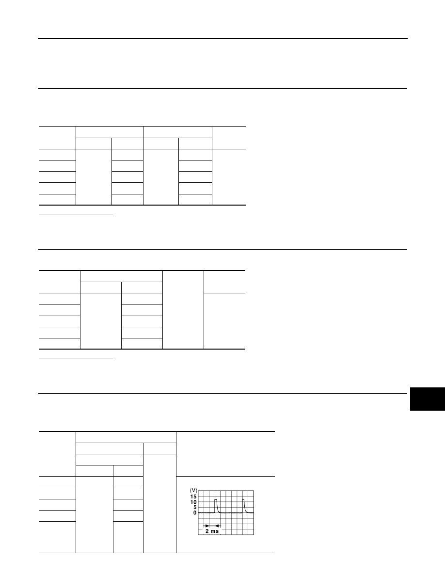
CHECK COMBINATION SWITCH OUTPUT VOLTAGE
1.
Connect the combination switch connector.
2.
Turn ON any switch in the system that is malfunctioning.
3.
Check voltage between combination switch harness connector and ground.
System
BCM
Combination switch
Continuity
Connector
Terminal
Connector
Terminal
OUTPUT 1
M123
143
M33
12
Existed
OUTPUT 2
144
14
OUTPUT 3
145
5
OUTPUT 4
146
2
OUTPUT 5
142
8
System
BCM
Ground
Continuity
Connector
Terminal
OUTPUT 1
M123
143
Not existed
OUTPUT 2
144
OUTPUT 3
145
OUTPUT 4
146
OUTPUT 5
142
System
Terminals
Value (Approx.)
(+)
(
−
)
Combination switch
Ground
Connector
Terminal
OUTPUT 1
M33
12
1.4 V
OUTPUT 2
14
OUTPUT 3
5
OUTPUT 4
2
OUTPUT 5
8
JPMIA0041GB