Index Infiniti Infiniti G35 (V35) Sedan - service repair manual 2007 year
Search
Content .. 183 184 185 186 ..
Infiniti G35 (V35) Sedan. Manual - part 185
AV-512
< ECU DIAGNOSIS >
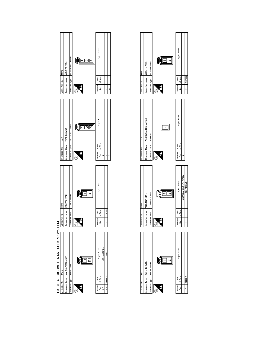
[BOSE AUDIO WITH NAVIGATION]
CD CHANGER
JCNWA0064GB