Infiniti G35 (V35) Sedan. Manual - part 159
AV-408
< ECU DIAGNOSIS >
[BOSE AUDIO WITH NAVIGATION]
AV CONTROL UNIT
40
(W)
Ground
Camera-connection recog-
nition signal
Input
Ignition
switch
ON
Connected to camera con-
trol unit connector
0 V
Not connected to camera
control unit connector
5 V
48
(G)
—
AV communication signal
(H)
Input/
Output
—
—
—
49
(R)
—
AV communication signal
(L)
Input/
Output
—
—
—
50
(V)
—
AV communication signal
(H)
Input/
Output
—
—
—
51
(LG)
—
AV communication signal
(L)
Input/
Output
—
—
—
52
(L)
—
CAN–H
Input/
Output
—
—
—
53
(P)
—
CAN–L
Input/
Output
—
—
—
61
(L)
Ground
RGB signal (R: red)
Output
Ignition
switch
ON
Start confirmation/adjust-
ment mode, and then dis-
play color bar by selecting
“Color Spectrum Bar” on
DISPLAY DIAGNOSIS
screen.
62
(O)
Ground
RGB signal (G: green)
Output
Ignition
switch
ON
Start confirmation/adjust-
ment mode, and then dis-
play color bar by selecting
“Color Spectrum Bar” on
DISPLAY DIAGNOSIS
screen.
63
(V)
Ground
RGB signal (B: blue)
Output
Ignition
switch
ON
Start confirmation/adjust-
ment mode, and then dis-
play color bar by selecting
“Color Spectrum Bar” on
DISPLAY DIAGNOSIS
screen.
64
—
Shield
—
—
—
—
65
(Y)
Ground
RGB synchronizing signal
Output
Ignition
switch
ON
—
66
—
Shield
—
—
—
—
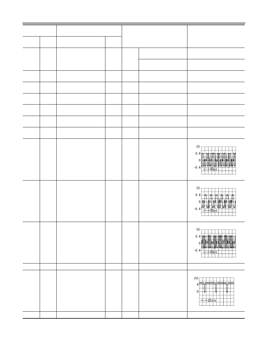
Terminal
(Wire color)
Description
Condition
Reference value
(Approx.)
+
–
Signal name
Input/
Output
SKIB2238J
SKIB2236J
SKIB2237J
SKIB3603E