Infiniti G35 (V35) Sedan. Manual - part 1383


  Index      Infiniti     Infiniti G35 (V35) Sedan - service repair manual 2007 year


Search            


Content   ..  1381  1382  1383  1384   ..


Infiniti G35 (V35) Sedan. Manual - part 1383


TM-224

< ON-VEHICLE MAINTENANCE >

[5AT: RE5R05A]

LINE PRESSURE TEST

LINE PRESSURE TEST

Inspection and Judgment

INFOID:0000000000957129

INSPECTION

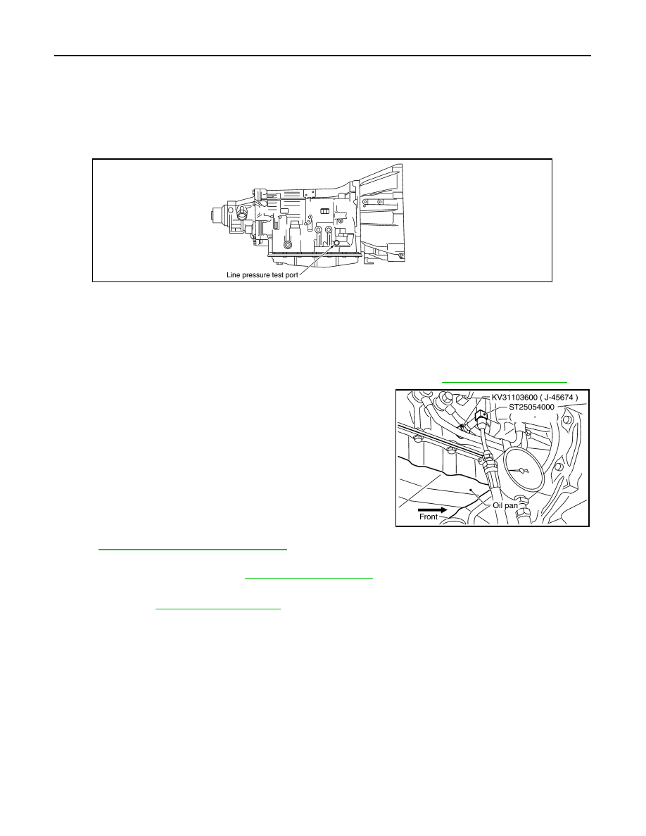
Line Pressure Test Port

Line Pressure Test Procedure

1.

Inspect the amount of engine oil and replenish if necessary.

2.

Drive the car for about 10 minutes to warm it up so that the ATF reaches in range of 50 to 80

°

C (122 to

176

°

F), then inspect the amount of ATF and replenish if necessary.

NOTE:
The A/T fluid temperature rises in range of 50 to 80

°

C (122 to 176

°

F) during 10 minutes of driving.

3.

Remove the front propeller shaft from vehicle (with AWD models). Refer to 

DLN-80, "Exploded View"

.

4.

After warming up remove the oil pressure detection plug and
install the oil pressure gauge [SST: ST2505S001(J-34301-C)].

CAUTION:

When using the oil pressure gauge, be sure to use the O-
ring attached to the oil pressure detection plug.

5.

Securely engage the parking brake so that the tires do not turn.

6.

Start the engine, then measure the line pressure at both idle and
the stall speed.

CAUTION:

• Keep the brake pedal pressed all the way down during

measurement.

• When measuring the line pressure at the stall speed, refer

to 

TM-223, "Inspection and Judgment"

7.

After the measurements are complete, install the oil pressure detection plug and tighten to the specified
torque. Refer to 

TM-281, "Exploded View"

.

CAUTION:

• Do not reuse O-ring.
• Apply ATF to O-ring.

JUDGMENT OF LINE PRESSURE TEST

SCIA2187E

LINE PRESSURE

: Refer to 

TM-353, "Line Pressure"

.

SCIA5309E

LINE PRESSURE TEST

TM-225

< ON-VEHICLE MAINTENANCE >

[5AT: RE5R05A]

C

E

F

G

H

I

J

K

L

M

A

B

TM

N

O

P

Judgment Possible 

cause

Idle speed

Low for all positions
(“P”, “R”, “N”, “D”, “M”)

Possible causes include malfunctions in the pressure supply system and low oil pump output.
For example
• Oil  pump  wear
• Pressure regulator valve or plug sticking or spring fatigue
• Oil  strainer 

 oil pump 

 pressure regulator valve passage oil leak

• Engine idle speed too low

Only low for a specific 
position

Possible causes include an oil pressure leak in a passage or device related to the position 
after the pressure is distributed by the manual valve.

High

Possible causes include a sensor malfunction or malfunction in the line pressure adjustment 
function.
For example
• Accelerator pedal position signal malfunction
• A/T fluid temperature sensor malfunction
• Line pressure solenoid malfunction (sticking in OFF state, filter clog, cut line)
• Pressure regulator valve or plug sticking

Stall speed

Oil pressure does not 
rise higher than the oil 
pressure for idle.

Possible causes include a sensor malfunction or malfunction in the pressure adjustment func-
tion.
For example
• Accelerator pedal position signal malfunction
• TCM breakdown
• Line pressure solenoid malfunction (shorting, sticking in ON state)
• Pressure regulator valve or plug sticking
• Pilot valve sticking or pilot filter clogged

The pressure rises, but 
does not enter the stan-
dard position.

Possible causes include malfunctions in the pressure supply system and malfunction in the 
pressure adjustment function.
For example
• Accelerator pedal position signal malfunction
• Line pressure solenoid malfunction (sticking, filter clog)
• Pressure regulator valve or plug sticking
• Pilot valve sticking or pilot filter clogged

Only low for a specific 
position

Possible causes include an oil pressure leak in a passage or device related to the position 
after the pressure is distributed by the manual valve.

TM-226

< ON-VEHICLE MAINTENANCE >

[5AT: RE5R05A]

ROAD TEST

ROAD TEST

Description

INFOID:0000000000957130

• The road test inspects overall performance of the A/T and analyzes possible malfunction causes.
• The road test is performed out in the following three stages.
1.

TM-226, "Check Before Engine Is Started"

2.

TM-226, "Check Starting The Engine"

.

3.

Cruise test

TM-227, "Cruise Test - Part 1"

TM-228, "Cruise Test - Part 2"

TM-228, "Cruise Test - Part 3"

CAUTION:

Always drive vehicle at a safe speed.

• Before beginning the road test, check the test procedure and inspection items.
• Test all inspection items until the symptom is uncovered. Diagnose NG items when all road tests are com-

plete.

Check Before Engine Is Started

INFOID:0000000000957131

1.

CHECK A/T CHECK INDICATOR LAMP

1.

Park vehicle on level surface.

2.

Shift the selector lever to “P” position.

3.

Turn ignition switch OFF and wait at least 10 seconds.

4.

Turn ignition switch ON. (Do not start engine.)

Does A/T CHECK indicator lamp light up for about 2 seconds?

YES

>> Go to 

TM-226, "Check Starting The Engine"

.

NO

>> Stop the road test and go to 

TM-191, "Symptom Table"

Check Starting The Engine

INFOID:0000000000957132

1.

CHECK STARTING THE ENGINE

1.

Park vehicle on level surface.

2.

Shift the selector lever to “P” or “N” position.

3.

Turn ignition switch OFF.

4.

Start the engine.

Does the engine start?

YES

>> GO TO 2.

NO

>> Stop the road test and go to 

TM-191, "Symptom Table"

.

2.

CHECK STARTING THE ENGINE

1.

Turn ignition switch ON. (Do not start engine.)

2.

Shift the selector lever to “D”, “M” or “R” position.

3.

Start the engine.

Does the engine start in any positions?

YES

>> Stop the road test and go to 

TM-191, "Symptom Table"

.

NO

>> GO TO 3.

3.

CHECK “P” POSITION FUNCTIONS

1.

Shift the selector lever to “P” position.

2.

Turn ignition switch OFF.

3.

Release the parking brake.

4.

Push the vehicle forward or backward.

5.

Engage the parking brake.

When you push the vehicle with disengaging the parking brake, does it move?

YES

>> Record the malfunction, then continue the rode test.

NO

>> GO TO 4. 

ROAD TEST

TM-227

< ON-VEHICLE MAINTENANCE >

[5AT: RE5R05A]

C

E

F

G

H

I

J

K

L

M

A

B

TM

N

O

P

4.

CHECK “N” POSITION FUNCTIONS

1.

Start the engine.

2.

Shift the selector lever to “N” position.

3.

Release the parking brake.

Does vehicle move forward or backward?

YES

>> Record the malfunction, then continue the rode test. 

NO

>> GO TO 5.

5.

CHECK SHIFT SHOCK

1.

Engage the brake.

2.

Shift the selector lever to “D” position.

When the A/T is shifted from “N” to “D”, is there an excessive shock?

YES

>> Record the malfunction, then continue the rode test.

NO

>> GO TO 6.

6.

CHECK “R” POSITION FUNCTIONS

1.

Shift the selector lever to “R” position.

2.

Release the brake for 4 to 5 seconds.

Does the vehicle creep backward?

YES

>> GO TO 7.

NO

>> Record the malfunction, then continue the rode test.

7.

CHECK “D” POSITION FUNCTIONS 

Inspect whether the vehicle creep forward when the A/T is put into the “D” position.

Does the vehicle creep forward in the “D” position?

YES

>> Go to 

TM-227, "Cruise Test - Part 1"

.

NO

>> Record the malfunction and go to 

TM-227, "Cruise Test - Part 1"

.

Cruise Test - Part 1

INFOID:0000000000957133

1.

CHECK STARTING OUT FROM D

1


1.

Drive the vehicle for about 10 minutes to warm up the engine oil and ATF.
Appropriate temperature for the ATF: 50 to 80

°

C (122 to 176

°

F)

2.

Park the vehicle on a level surface.

3.

Shift the selector lever to “D” position.

4.

Press the accelerator pedal about half way down to accelerate the vehicle.

  With CONSULT-III

Read the value of “GEAR” with “DATA MONITOR” mode. Refer to 

TM-114, "CONSULT-III Function (TRANS-

MISSION)"

.

Starts from D

1

?

YES

>> GO TO 2.

NO

>> Record the malfunction, then continue the road test.

2.

CHECK SHIFT-UP

Depress the accelerator pedal about half-way and inspect if the vehicle shifts up (D

1


 D

2


 D

3


 D

4


 D

5

)

at the appropriate speed. Refer to 

TM-353, "Vehicle Speed at Which Gear Shifting Occurs"

.

  With CONSULT-III

Read the value of “GEAR”, “ACCELE POSI” and “VEHCLE SPEED” with “DATA MONITOR” mode. Refer to

TM-114, "CONSULT-III Function (TRANSMISSION)"

.

Is the inspection result normal?

YES

>> GO TO 3.

NO

>> Record the malfunction, then continue the road test.

3.

CHECK LOCK-UP 

When releasing accelerator pedal (closed throttle position signal OFF) from D

5

, check lock-up from D

5

 to L/U.

Refer to 

TM-353, "Vehicle Speed at Which Lock-up Occurs/Releases"

.


Content   ..  1381  1382  1383  1384   ..