Content .. 1332 1333 1334 1335 ..
Infiniti G35 (V35) Sedan. Manual - part 1334
TM-28
< REMOVAL AND INSTALLATION >
[6MT: FS6R31A]
TRANSMISSION ASSEMBLY
g.
Remove guide plate mounting bolts and then remove control
lever assembly and control lever spring from control lever hous-
ing.
CAUTION:
Restrain guide plate while doing this because there is a
danger control lever assembly will fly out of control lever
housing.
7.
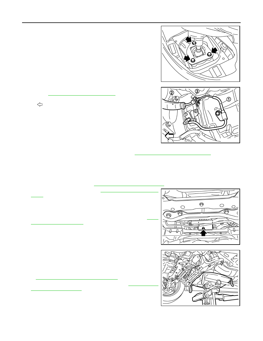
Remove clutch tube (1), clutch hose (2), and lock plate (3).
Refer to
CL-13, "Removal and Installation"
CAUTION:
• Keep painted surface on the body or other parts free of
clutch fluid. If it spills, wipe up immediately and wash the
affected area with water.
• Do not depress clutch pedal during removal procedure.
NOTE:
Insert a suitable plug into clutch hose and CSC (Concentric
Slave Cylinder) tube after removing clutch tube.
8.
Remove crankshaft position sensor (POS). Refer to
EM-114, "Disassembly and Assembly"
CAUTION:
• Handle carefully to avoid dropping and shocks.
• Do not disassemble.
• Do not allow metal powder to adhere to magnetic part at sensor tip.
• Do not place sensors in a location where they are exposed to magnetism.
9.
Remove starter motor. Refer to
STR-16, "Removal and Installation"
.
10. Remove rear plate cover. Refer to
.
11. Disconnect park/neutral position (PNP) switch harness connec-
tor.
12. Disconnect heated oxygen sensor 2 (bank 1) and heated oxy-
gen sensor 2 (bank 2) harness connectors. Refer to
13. Remove harness brackets.
14. Set a suitable jack to the transmission assembly.
CAUTION:
When setting a suitable jack, be careful so that it does not
contact with the switch.
15. Remove engine mounting insulator (rear) mounting nuts. Refer
EM-77, "2WD : Removal and Installation"
.
16. Remove rear engine mounting member. Refer to
.
17. Remove engine and transmission mounting bolts with power
tool.
18. Lower a suitable jack to the position where the back-up lamp
switch harness connector can be disconnect. Then disconnect back-up lamp switch harness connector.
19. Remove transmission assembly from the vehicle.
CAUTION:
JPDIC0022ZZ
: Vehicle front
JPDIC0026ZZ
JPDIC0024ZZ
JPDIC0023ZZ