Infiniti G35 (V35) Sedan. Manual - part 1326


  Index      Infiniti     Infiniti G35 (V35) Sedan - service repair manual 2007 year


Search            


Content   ..  1324  1325  1326  1327   ..


Infiniti G35 (V35) Sedan. Manual - part 1326


STR-14

< PREPARATION >

PREPARATION

PREPARATION

PREPARATION

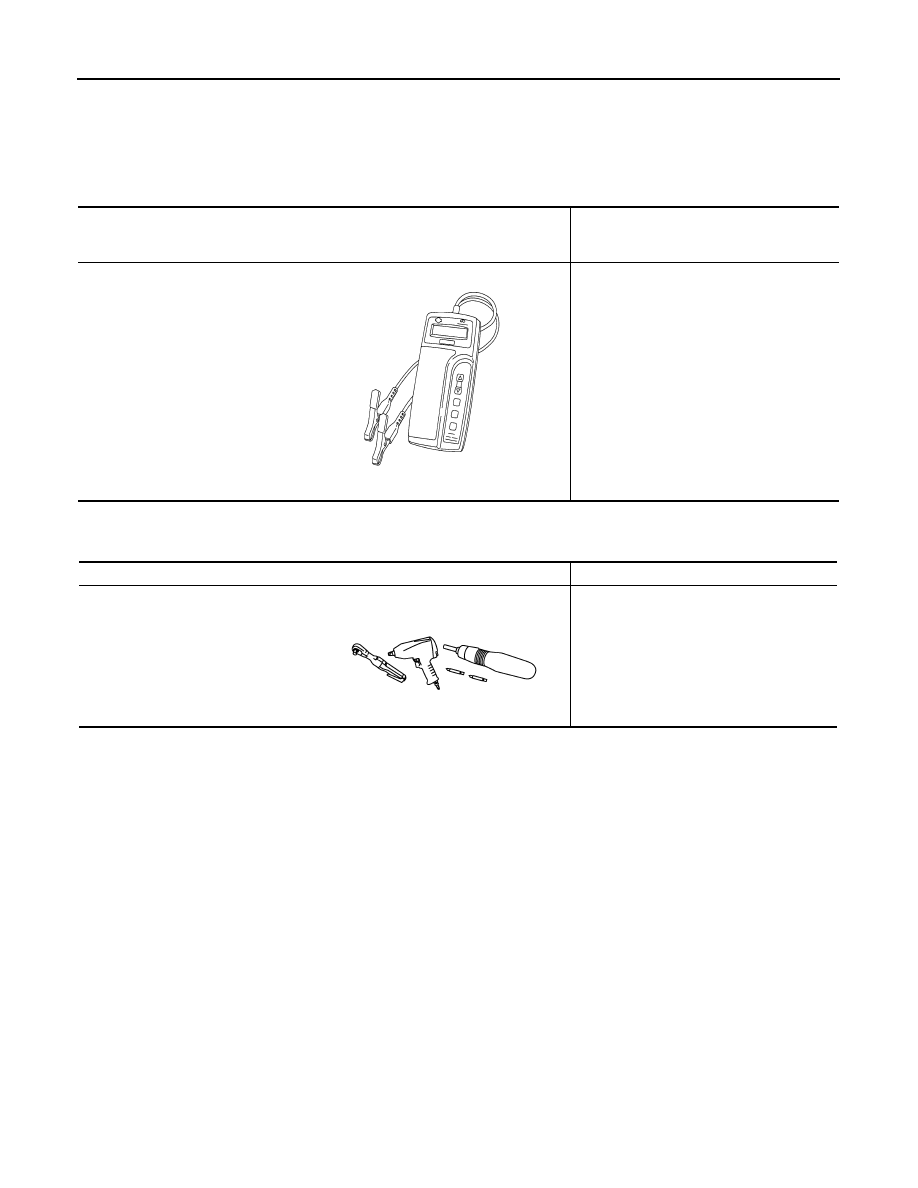
Special Service Tool

INFOID:0000000000956397

Commercial Service Tool

INFOID:0000000000956398

Tool number
(Kent-Moore No.)
Tool name

Description

(J-44373 Model MCR620)
Starting/Charging System Tester

Tests starting and charging systems.
For operating instructions, refer to Technical 
Service Bulletin.

SEL403X

Tool name

Description

Power tool

Loosening bolts, nuts and screws

PIIB1407E

STARTER MOTOR

STR-15

< ON-VEHICLE REPAIR >

C

D

E

F

G

H

I

J

K

L

M

A

STR

N

P

O

ON-VEHICLE REPAIR

STARTER MOTOR

Exploded View

INFOID:0000000000956399

REMOVAL

DISASSEMBLY

Type: S114-927

1.

“B” terminal nut

2.

“B” terminal harness

3.

Starter motor

4.

Harness clip bracket

5.

Starter motor mounting bolt

6.

Converter housing (A/T models)
Transmission case (M/T models)

7.

“S” connector

 : Engine front

Refer to 

GI-4, "Components"

 for symbols in the figure.

JPBIA0147GB

STR-16

< ON-VEHICLE REPAIR >

STARTER MOTOR

Removal and Installation

INFOID:0000000000956400

REMOVAL

1.

Disconnect the battery cable from the negative terminal.

2.

Remove engine undercover, using power tools.

3.

Remove exhaust mounting bracket. Refer to 

EX-5, "Exploded View"

4.

Disconnect steering lower joint (1), then remove it. Refer to 

ST-

20, "WITHOUT 4WAS : Exploded View"

 (Without 4WAS) or 

ST-

21, "WITH 4WAS : Exploded View"

 (With 4WAS).

5.

Remove “B” terminal nut (A).

1.

Magnetic switch assembly

2.

Dust cover kit

3.

Shift lever set

4.

Center bracket (A)

5.

Yoke assembly

6.

Armature assembly

7.

Brush holder assembly

8.

Thrust washer

9.

Rear cover assembly

10. Shaft gear assembly

11.

Packing

12. Thrust washer

13. Center bracket (P)

14. E-ring

15. Pinion assembly

16. Pinion stopper

17. Pinion stopper clip

18. Gear case assembly

 : High-temperature grease point

Refer to 

GI-4, "Components"

 for symbols not described on the above.

JPBIA0148GB

JSBIA0003ZZ

STARTER MOTOR

STR-17

< ON-VEHICLE REPAIR >

C

D

E

F

G

H

I

J

K

L

M

A

STR

N

P

O

6.

Disconnect “S” connector (B).

7.

Remove starter motor mounting bolts (A), using power tools.

8.

Remove starter motor (1) downward from the vehicle.

INSTALLATION

Install in the reverse order of removal.

CAUTION:

Be sure to tighten “B” terminal nut carefully.

Inspection

INFOID:0000000000956401

INSPECTION AFTER DISASSEMBLY

Pinion/Clutch Check

1.

Inspect pinion teeth.
• Replace pinion if teeth are worn or damaged. (Also check condition of ring gear teeth.)

2.

Inspect reduction gear teeth.
• Replace reduction gear if teeth are worn or damaged. (Also check condition of armature shaft gear

teeth.)

3.

Check to see if pinion locks in one direction and rotates smoothly in the opposite direction.
• If it locks or rotates in both directions, or unusual resistance is evident, replace.

JSBIA0004ZZ

JSBIA0002ZZ


Content   ..  1324  1325  1326  1327   ..