Infiniti G35 (V35) Sedan. Manual - part 1266


  Index      Infiniti     Infiniti G35 (V35) Sedan - service repair manual 2007 year


Search            


Content   ..  1264  1265  1266  1267   ..


Infiniti G35 (V35) Sedan. Manual - part 1266


ST-14

< ON-VEHICLE MAINTENANCE >

STEERING WHEEL

4.

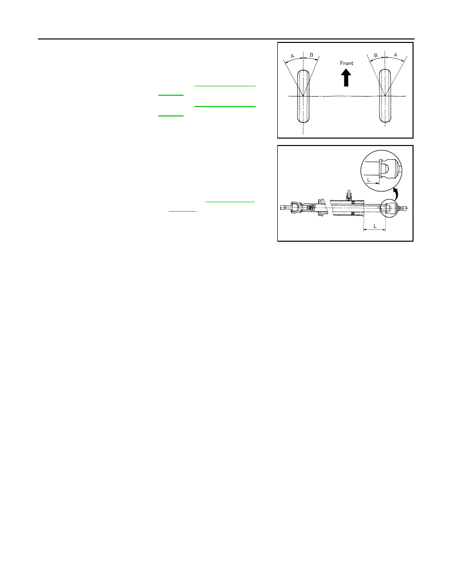
With the engine at idle, turn steering wheel from full left stop to
full right stop and measure the turning angles.

5.

Check the following items when turning angle is out of the stan-
dard.

a.

Check rack stroke.

b.

Disassemble steering gear assembly to check the cause that
rack stroke is outside of the standard.
• Steering angles are not adjustable. Check steering gear

assembly, steering column assembly and front suspension
components for wear or damage if any of the turning angles are different from the specified value.
Replace any of them, if any non-standard condition exists.

Standard

Inner wheel (Angle: A)

: Refer to 

ST-58, "Steering 

Angle"

.

Outer wheel (Angle: B)

: Refer to 

ST-58, "Steering 

Angle"

.

SGIA0055E

Standard

Rack stroke “L”

: Refer to 

ST-59, "Rack 

Stroke"

.

SGIA0629J

STEERING WHEEL

ST-15

< ON-VEHICLE REPAIR >

C

D

E

F

H

I

J

K

L

M

A

B

ST

N

O

P

ON-VEHICLE REPAIR

STEERING WHEEL

Exploded View

INFOID:0000000000958659

Removal and Installation

INFOID:0000000000958660

REMOVAL

NOTE:
When reconnecting spiral cable, fix cable with a tape so that fixing case and rotating part keep aligned. This
will omit neutral position alignment procedure during spiral cable installation.
1.

Set vehicle to the straight-ahead position.

2.

Remove driver air bag module. Refer to 

SR-4, "Removal and Installation"

.

3.

Remove steering wheel lock nut after steering is locked.

4.

Remove steering wheel with the steering wheel puller (A) [SST:
ST27180001 (J-25726-A)].

INSTALLATION

Note the following, and install in the reverse order of removal.

CAUTION:

Never twist spiral cable freely on excessively after it becomes tight (doing so may cause the cable to
be turn off).
NOTE:
Check the spiral cable neutral position after replacing or rotating spiral cable. Refer to 

SR-7, "Removal and

Installation"

.

1.

Steering wheel

Refer to 

GI-4, "Components"

 for symbols in the figure.

JSGIA0026GB

SGIA1323E

ST-16

< ON-VEHICLE REPAIR >

STEERING COLUMN

STEERING COLUMN

MANUAL TYPE

MANUAL TYPE : Exploded View

INFOID:0000000000958661

MANUAL TYPE : Removal and Installation

INFOID:0000000000958662

REMOVAL

1.

Set vehicle to the straight-ahead position.

2.

Place the tilt to the highest level. Place the telescopic to the longest level.

3.

Remove driver air bag module. Refer to 

SR-4, "Removal and Installation"

.

4.

Remove steering wheel. Refer to 

ST-15, "Exploded View"

.

5.

Remove steering column cover. Refer to 

IP-12, "Removal and Installation"

.

6.

Remove spiral cable. Refer to 

SR-7, "Removal and Installation"

.

7.

Remove combination switch. Refer to 

MWI-156, "Removal and Installation"

.

8.

Remove instrument driver lower panel. Refer to 

IP-12, "Removal and Installation"

.

9.

Remove knee protector (1).

10. Remove combination meter. Refer to 

MWI-156, "Removal and

Installation"

.

11. Disconnect each switch harness connectors installed to steering

column assembly.

12. Remove the joint mounting bolt and nut (lower shaft side), and

separate the joint from lower shaft.

13. Remove steering column assembly.

CAUTION:

• Never give axial impact to steering column assembly dur-

ing removal.

• Never move steering gear assembly when removing steering column assembly.

INSTALLATION

Note the following, and install in the reverse order of removal.
• Be careful of the following points when installing the steering column assembly.

CAUTION:

1.

Steering column assembly

Refer to 

GI-4, "Components"

 for symbols in the figure.

JSGIA0028GB

JSGIA0030ZZ

STEERING COLUMN

ST-17

< ON-VEHICLE REPAIR >

C

D

E

F

H

I

J

K

L

M

A

B

ST

N

O

P

• Never give axial impact to steering column assembly during installation.
• Never move steering gear assembly.
• Never reuse the joint mounting nut (lower shaft side).

• Adjust neutral position of steering angle sensor. Refer to 

BRC-8, "ADJUSTMENT OF STEERING ANGLE

SENSOR NEUTRAL POSITION : Special Repair Requirement"

.

MANUAL TYPE : Inspection

INFOID:0000000000958663

INSPECTION AFTER REMOVAL

• Check each part of steering column assembly for damage or other malfunctions. Replace if there are.
• Measure steering column assembly rotating torque using a preload gauge [SST: ST3127S000 (J-25765-A)].

Replace steering column assembly if outside the standard.

INSPECTION AFTER INSTALLATION

• Check each part of steering column assembly for damage or other malfunctions. Replace if there are.
• Check the steering wheel play, neutral position steering wheel, steering wheel turning force, and front wheel

turning angle. Refer to 

ST-12, "Inspection"

.

• Check tilt and telescopic mechanism operating range “L”, “T” as

shown in the figure.

AUTOMATIC

AUTOMATIC : Exploded View

INFOID:0000000000958664

Standard

Rotating torque

: Refer to 

ST-58, "Steering 

Column Operating 
Range"

.

Standard

Tilt operating range “T”

: Refer to 

ST-58, "Steering 

Column Operating 
Range"

.

Telescopic operating 
range “L”

: Refer to 

ST-58, "Steering 

Column Operating 
Range"

.

JSGIA0033ZZ

1.

Upper stay

2.

Clip

3.

Steering column assembly

4.

Clip

JSGIA0029GB


Content   ..  1264  1265  1266  1267   ..