Infiniti G35 (V35) Sedan. Manual - part 1110


  Index      Infiniti     Infiniti G35 (V35) Sedan - service repair manual 2007 year


Search            


Content   ..  1108  1109  1110  1111   ..


Infiniti G35 (V35) Sedan. Manual - part 1110


RF-10

< COMPONENT DIAGNOSIS >

POWER SUPPLY AND GROUND CIRCUIT

4.

Check continuity between BCM connector and ground.

Is the inspection result normal?

YES

>> GO TO 4.

NO

>> Repair or replace harness.

4.

CHECK BCM OUTPUT SIGNAL

1.

Connect BCM connector.

2.

Turn ignition switch ON.

3.

Check voltage between BCM connector and ground.

Is the measurement value within the specification?

YES

>> Check condition of harness and connector.

NO

>> Replace BCM. Refer to 

BCS-79, "Removal and Installation"

.

5.

CHECK SUNROOF SWITCH INPUT SIGNAL 

1.

Connect sunroof motor assembly connector.

2.

Turn ignition switch ON.

3.

Check voltage between sunroof motor assembly connector and ground.

Is the measurement value within the specification?

YES

>> GO TO 8.

NO

>> GO TO 6.

6.

CHECK SUNROOF SWITCH CIRCUIT

1.

Turn ignition switch OFF.

2.

Disconnect sunroof motor assembly connector and sunroof switch connector.

3.

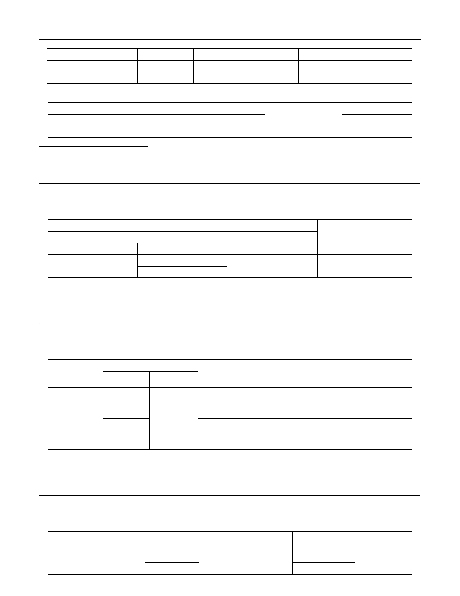
Check continuity between sunroof motor assembly connector and sunroof switch connector.

BCM connector

Terminal

Sunroof motor assembly connector

Terminal

Continuity

M118

2

R4

7

Existed

3

9

BCM connector

Terminal

Ground

Continuity

M118

2

Not existed

3

Terminals

Voltage (V)

(Approx.)

(+)

(–)

BCM connector

Terminal 

M118

2

Ground

Battery voltage

3

Sunroof motor 

assembly con-

nector

Terminals

Condition

Voltage (V)

(Approx.)

(+)

(–)

R4

5

Ground

Sunroof switch is operated
TILT DOWN or SLIDE OPEN

0

Other than above

Battery voltage

1

Sunroof switch is operated 
TILT UP or SLIDE CLOSE

0

Other than above

Battery voltage

Sunroof motor assembly con-

nector

Terminal

Sunroof switch connector

Terminal

Continuity

R4

5

R16

1

Existed

1

3

POWER SUPPLY AND GROUND CIRCUIT

RF-11

< COMPONENT DIAGNOSIS >

C

D

E

F

G

H

I

J

L

M

A

B

RF

N

O

P

4.

Check continuity between sunroof motor assembly connector and ground. 

Is the inspection result normal?

YES

>> GO TO 7.

NO

>> Repair or replace harness.

7.

CHECK SUNROOF SWITCH GROUND CIRCUIT

Check continuity between sunroof switch connector and ground.

Is the inspection result normal?

YES

>> Refer to 

RF-11, "SUNROOF MOTOR ASSEMBLY : Component Inspection"

.

NO

>> Repair or replace harness.

8.

CHECK UNIFIED METER AND A/C AMP. SIGNAL 

1.

Connect sunroof motor assembly connector.

2.

Turn ignition switch ON.

3.

Check signal between sunroof motor assembly connector and ground with oscilloscope.

Is the inspection result normal?

YES

>> Replace sunroof motor assembly. Refer to 

RF-67, "Removal and Installation"

. After that, 

RF-12,

"SUNROOF MOTOR ASSEMBLY : Special Repair Requirement"

.

NO

>> GO TO 9.

9.

CHECK UNIFIED METER AND A/C AMP. CIRCUIT

1.

Turn ignition switch OFF.

2.

Disconnect unified meter and A/C amp. connector.

3.

Check continuity between unified meter and A/C amp. connector and sunroof motor assembly connector.

4.

Check continuity between unified meter and A/C amp. connector and ground.

Is the inspection result normal?

YES

>> Replace Unified meter and A/C amp. Refer to 

MWI-158, "Removal and Installation"

.

NO

>> Repair or replace harness.

SUNROOF MOTOR ASSEMBLY : Component Inspection

INFOID:0000000000961753

Sunroof motor assembly connector

Terminal

Ground

Continuity

R4

5

Not existed

1

Sunroof switch connector

Terminal

Ground

Continuity 

R16

2

Existed

 Sunroof motor assembly connector

Terminal

Ground

Condition 

 Signal

(Reference value)

R4

8

Speed meter operated [When 

vehicle speed is approx.40km/

h (25MPH)]

ELF1080D

Unified meter and A/C amp. con-

nector

Terminal

Sunroof motor assembly con-

nector

Terminal

Continuity

M66

8

R4

8

Existed

Unified meter and A/C amp. connector

Terminal

Ground

Continuity 

M66

8

Not existed

RF-12

< COMPONENT DIAGNOSIS >

POWER SUPPLY AND GROUND CIRCUIT

SUNROOF SWITCH

1.

CHECK SUNROOF SWITCH

1.

Turn ignition switch OFF.

2.

Disconnect sunroof switch connector.

3.

Check continuity between sunroof switch terminals.

Is the inspection result normal?

YES

>> Sunroof switch is OK.

NO

>> Replace sunroof switch (map lamp assembly). Refer to 

INT-23, "Removal and Installation"

SUNROOF MOTOR ASSEMBLY : Special Repair Requirement

INFOID:0000000000961754

1.

PERFORM INITIALIZATION PROCEDURE

Perform initialization procedure. 
Refer to 

RF-4, "ADDITIONAL SERVICE WHEN REPLACING CONTROL UNIT : Special Repair Requirement"

.

Is the inspection result normal?

YES

>> GO TO 2.

NO

>> Check intermittent incident. Refer to 

GI-39, "Intermittent Incident"

.

2.

CHECK ANTI-PINCH OPERATION 

Check anti-pinch operation.
Refer to 

RF-4, "ADDITIONAL SERVICE WHEN REPLACING CONTROL UNIT : Special Repair Requirement"

.

Is the inspection result normal?

YES

>> Inspection end.

NO

>> Check fitting adjustment. Refer to 

RF-69, "Adjustment"

.

Terminals

Condition

Continuity

2

Sunroof switch is operated 
TILT DOWN or SLIDE OPEN

Existed

Other than above

Not existed

3

Sunroof switch is operated
TILT UP or SLIDE CLOSE

Existed

Other than above

Not existed

DOOR SWITCH

RF-13

< COMPONENT DIAGNOSIS >

C

D

E

F

G

H

I

J

L

M

A

B

RF

N

O

P

DOOR SWITCH

Description

INFOID:0000000000961755

Detects door open/close condition and transmits the signal to BCM.

Component Function Check

INFOID:0000000000961756

1.

CHECK DOOR SWITCH INPUT SIGNAL

Check (“DOOR SW-DR” and “DOOR SW-AS”) in “DATA MONITOR” mode with CONSULT-III.

Is the inspection result normal?

YES

>> Door switch circuit is OK.

NO

>> Refer to 

RF-13, "Diagnosis Procedure"

.

Diagnosis Procedure

INFOID:0000000000961757

1.

CHECK FRONT DOOR SWITCH INPUT SIGNAL

Check voltage between BCM connector and ground.

Is the measurement value within the specification?

YES

>> Replace BCM. Refer to 

BCS-79, "Removal and Installation"

.

NO

>> GO TO 2.

2.

CHECK HARNESS CONTINUITY

1.

Turn ignition switch OFF.

2.

Disconnect BCM connector and front door switch connector.

3.

Check continuity between BCM connector and front door switch connector.

4.

Check continuity between BCM connector and ground.

Is the inspection result normal?

YES

>> GO TO 3.

Monitor item

Condition

DOOR SW-DR

OPEN

: ON

CLOSE

: OFF

DOOR SW-AS

OPEN

: ON

CLOSE

: OFF

Terminals

Door condition

Voltage (V)

(Approx.)

(+)

(–)

BCM connector

Terminal 

M123

124

Ground

Passenger side

OPEN

0

CLOSE

Battery voltage

150

Driver side

OPEN

0

CLOSE

Battery voltage

BCM connector

Terminal

Front door switch connector

Terminal

Continuity

M123

124

Passenger side

B116

2

Existed

150

Driver side

B16

BCM connector

Terminal

Ground

Continuity

M123

124

Not existed

150


Content   ..  1108  1109  1110  1111   ..