Content .. 1033 1034 1035 1036 ..
Infiniti G35 (V35) Sedan. Manual - part 1035
PG-72
< COMPONENT DIAGNOSIS >
[POWER SUPPLY&GROUND CIRCUIT]
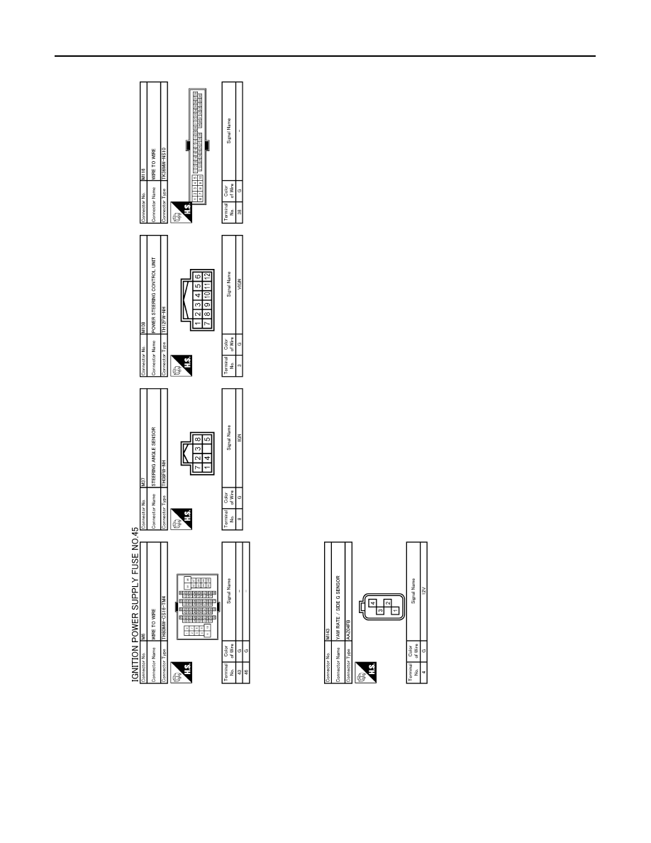
POWER SUPPLY ROUTING CIRCUIT
Fuse
INFOID:0000000000964300
JCMWA0105GB
|
|
|
Content .. 1033 1034 1035 1036 ..
PG-72 < COMPONENT DIAGNOSIS > [POWER SUPPLY&GROUND CIRCUIT] POWER SUPPLY ROUTING CIRCUIT Fuse INFOID:0000000000964300 JCMWA0105GB |