Infiniti G35 (V35) Sedan. Manual - part 68


  Index      Infiniti     Infiniti G35 (V35) Sedan - service repair manual 2007 year


Search            


Content   ..  66  67  68  69   ..


Infiniti G35 (V35) Sedan. Manual - part 68


AV-44

< COMPONENT DIAGNOSIS >

[BASE AUDIO WITHOUT NAVIGATION]

RGB (B: BLUE) SIGNAL CIRCUIT

RGB (B: BLUE) SIGNAL CIRCUIT

Description

INFOID:0000000000964557

Transmit the image displayed with AV control unit with RGB signal to the display unit.

Diagnosis Procedure

INFOID:0000000000964558

1.

CHECK CONTINUITY RGB (B: BLUE) SIGNAL CIRCUIT

1.

Turn ignition switch OFF.

2.

Disconnect display unit connector and AV control unit connector.

3.

Check continuity between display unit harness connector terminal 18 and AV control unit harness connec-
tor terminal 38.

4.

Check continuity between display unit harness connector terminal 18 and ground.

Is inspection result OK?

YES

>> GO TO 2.

NO

>> Repair harness or connector.

2.

CHECK RGB (B: BLUE) SIGNAL

1.

Connect display unit connector and AV control unit connector.

2.

Turn ignition switch ON.

3.

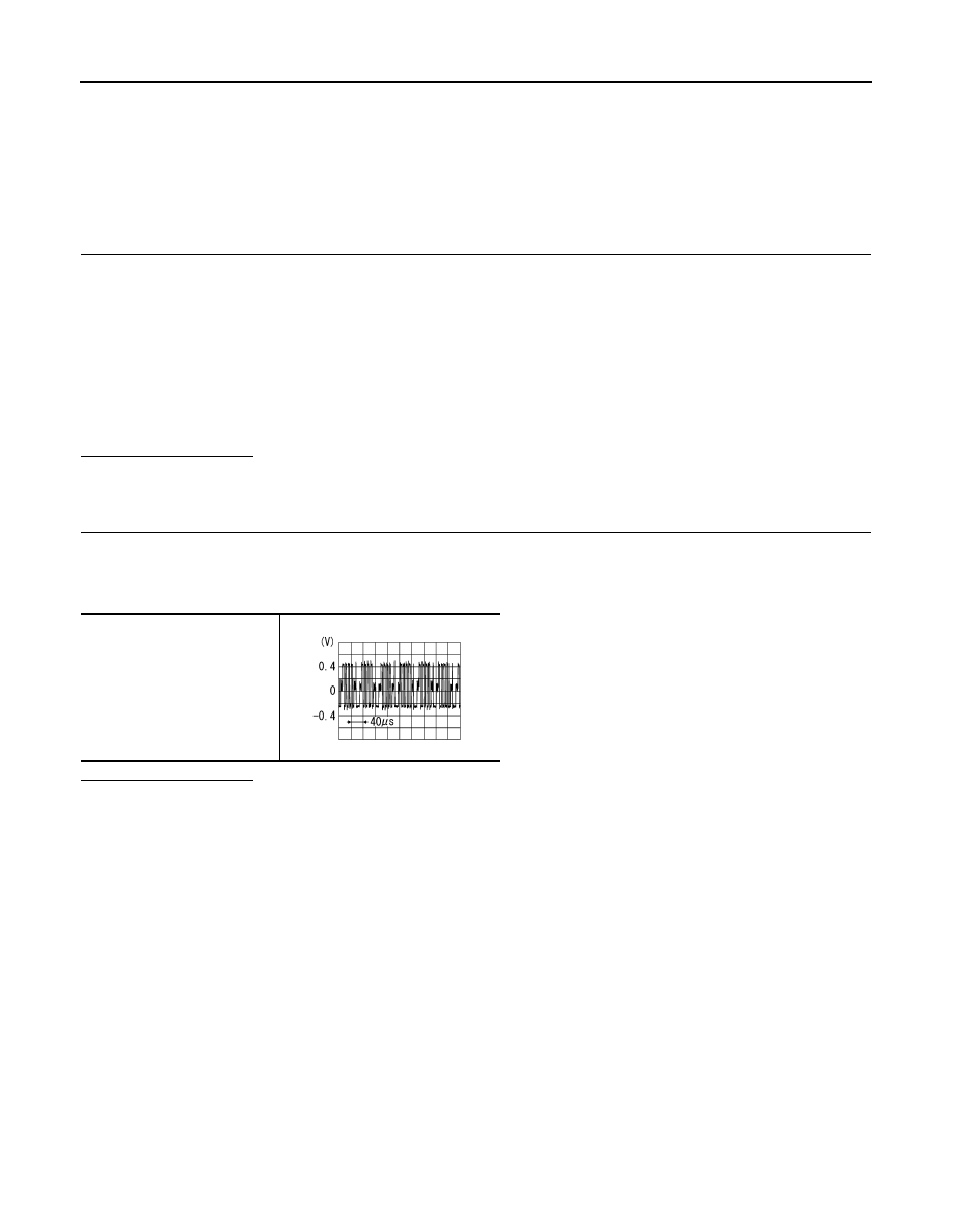
Check signal between display unit harness connector terminal 18 and ground.

Is inspection result OK?

YES

>> Replace display unit.

NO

>> Replace AV control unit.

18 - 38

: Continuity should exist.

18 - Ground

: Continuity should not exist.

18 - Ground

SKIB2237J

AV

RGB SYNCHRONIZING SIGNAL CIRCUIT

AV-45

< COMPONENT DIAGNOSIS >

[BASE AUDIO WITHOUT NAVIGATION]

C

D

E

F

G

H

I

J

K

L

M

B

N

A

O

P

RGB SYNCHRONIZING SIGNAL CIRCUIT

Description

INFOID:0000000000964559

Transmit the RGB synchronizing signal to the display unit so as to synchronize the RGB image displayed with
AV control unit.

Diagnosis Procedure

INFOID:0000000000964560

1.

CHECK CONTINUITY RGB SYNCHRONIZING SIGNAL CIRCUIT

1.

Turn ignition switch OFF.

2.

Disconnect display unit connector and AV control unit connector.

3.

Check continuity between display unit harness connector terminal 19 and AV control unit harness connec-
tor terminal 41.

4.

Check continuity between display unit harness connector terminal 19 and ground.

Is inspection result OK?

YES

>> GO TO 2.

NO

>> Repair harness or connector.

2.

CHECK RGB SYNCHRONIZING SIGNAL

1.

Connect display unit connector and AV control unit connector.

2.

Turn ignition switch ON.

3.

Check signal between display unit harness connector terminal 19 and ground.

Is inspection result OK?

YES

>> Replace display unit.

NO

>> Replace AV control unit.

19 - 41

: Continuity should exist.

19 - Ground

: Continuity should not exist.

19 - Ground

SKIB3603E

AV-46

< COMPONENT DIAGNOSIS >

[BASE AUDIO WITHOUT NAVIGATION]

RGB AREA (YS) SIGNAL CIRCUIT

RGB AREA (YS) SIGNAL CIRCUIT

Description

INFOID:0000000000964561

Transmits the display area of RGB image displayed by AV control unit with RGB area (YS) signal to display
unit.

Diagnosis Procedure

INFOID:0000000000964562

1.

CHECK CONTINUITY RGB AREA (YS) SIGNAL CIRCUIT

1.

Turn ignition switch OFF.

2.

Disconnect display unit connector and AV control unit connector.

3.

Check continuity between display unit harness connector terminal 9 and AV control unit harness connec-
tor terminal 43.

4.

Check continuity between display unit harness connector terminal 9 and ground.

Is inspection result OK?

YES

>> GO TO 2.

NO

>> Repair harness or connector.

2.

CHECK RGB SYNCHRONIZING SIGNAL

1.

Connect display unit connector and AV control unit connector.

2.

Turn ignition switch ON.

3.

Check signal between display unit harness connector terminal 9 and ground.

Is inspection result OK?

YES

>> Replace display unit.

NO

>> Replace AV control unit.

9 - 43

: Continuity should exist.

9 - Ground

: Continuity should not exist.

9 - Ground

At RGB image displayed

: Approx. 5 V

At rear view camera image displayed

PKIB4948J

AV

HORIZONTAL SYNCHRONIZING (HP) SIGNAL CIRCUIT

AV-47

< COMPONENT DIAGNOSIS >

[BASE AUDIO WITHOUT NAVIGATION]

C

D

E

F

G

H

I

J

K

L

M

B

N

A

O

P

HORIZONTAL SYNCHRONIZING (HP) SIGNAL CIRCUIT

Description

INFOID:0000000000964563

In composite image (AUX image, camera image), transmit the vertical synchronizing (VP) signal and horizon-
tal synchronizing (HP) signal from display unit to AV control unit so as to synchronize the RGB images dis-
played with AV control unit such as the image quality adjusting menu, etc.

Diagnosis Procedure

INFOID:0000000000964564

1.

CHECK CONTINUITY HORIZONTAL SYNCHRONIZING (HP) SIGNAL CIRCUIT

1.

Turn ignition switch OFF.

2.

Disconnect display unit connector and AV control unit connector.

3.

Check continuity between display unit harness connector terminal 8 and AV control unit harness connec-
tor terminal 45.

4.

Check continuity between display unit harness connector terminal 8 and ground.

Is inspection result OK?

YES

>> GO TO 2.

NO

>> Repair harness or connector.

2.

CHECK HORIZONTAL SYNCHRONIZING (HP) SIGNAL

1.

Connect display unit connector and AV control unit connector.

2.

Turn ignition switch ON.

3.

Check signal between display unit harness connector terminal 8 and ground.

Is inspection result OK?

YES

>> Replace AV control unit.

NO

>> Replace Display unit.

8 - 45

: Continuity should exist.

8 - Ground

: Continuity should not exist.

8 - Ground

SKIB3601E


Content   ..  66  67  68  69   ..