Infiniti G35 (V35) Sedan. Manual - part 63


  Index      Infiniti     Infiniti G35 (V35) Sedan - service repair manual 2007 year


Search            


Content   ..  61  62  63  64   ..


Infiniti G35 (V35) Sedan. Manual - part 63


AV-24

< FUNCTION DIAGNOSIS >

[BASE AUDIO WITHOUT NAVIGATION]

DIAGNOSIS SYSTEM (AV CONTROL UNIT)

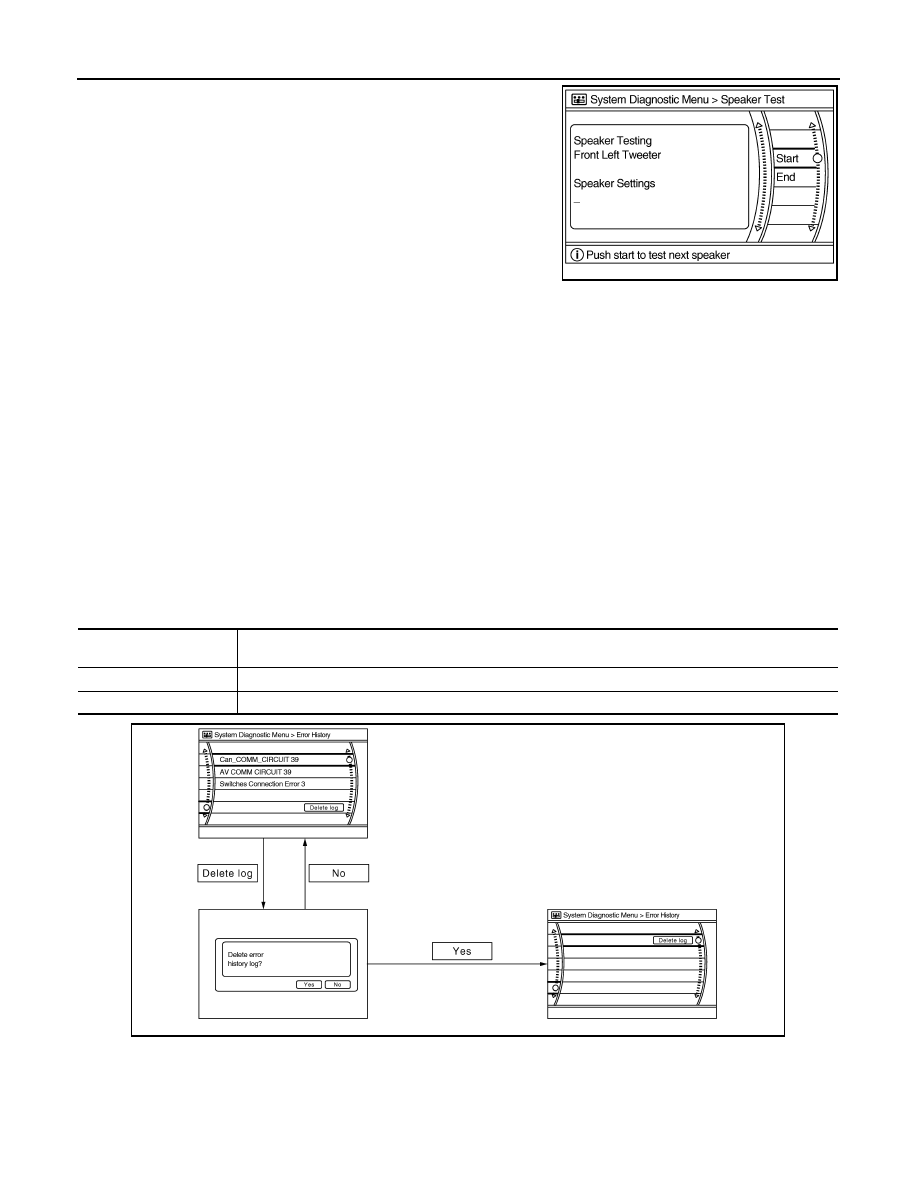
Select “SPEAKER DIAGNOSIS” to display the Speaker Diagnosis
screen. Press “START and NEXT” to generate a test tone in a
speaker. Press “Start” to generate a test tone in the next speaker.
Press “End” to stop the test tones.
NOTE:
The frequency of test tone emitted from each speaker is as follows.

Climate Control

Refer to “HEATER & AIR CONDITIONING CONTROL SYSTEM” for details.

Error History

The self-diagnosis results are judged depending on whether any error occurs from when “Self-diagnosis” is
selected until the self-diagnosis results are displayed.
However, the diagnosis results are judged normal if an error has occurred before the ignition SW is turned ON
and then no error has occurred until the self-diagnosis start. Check the “Error Record” to detect any error that
may have occurred before the self-diagnosis start because of this situation.
Count up method A
• The counter resets to 0 if an error occurs when IGN switch is turned ON. The counter increases by 1 if the

condition is normal at a next IGN ON cycle. 

• The counter upper limit is 39. Any counts exceeding 39 are ignored. The counter can be reset (no error

record display) with the “Delete log” switch or CONSULT-III.

Count up method B
• The counter increases by 1 if an error occurs when IGN switch is ON. The counter will not decrease even if

the condition is normal at the next IGN ON cycle. 

• The counter upper limit is 50. Any counts exceeding 50 are ignored. The counter can be reset (no error

record display) with the “Delete log” switch or CONSULT-III.

Error item
Some error items may be displayed simultaneously according to the cause. If some error items are displayed
simultaneously, the detection of the cause can be performed by the combination of display items

Tweeter

: 3 kHz

Front door speaker

: 300 Hz

Rear door speaker

: 1 kHz

JSNIA0150GB

Display type of occur-

rence frequency

Error history display item

Count up method A

CAN communication line, control unit (CAN), AV communication line, control unit (AV communication)

Count up method B

Other than the above

JSNIA0151GB

AV

DIAGNOSIS SYSTEM (AV CONTROL UNIT)

AV-25

< FUNCTION DIAGNOSIS >

[BASE AUDIO WITHOUT NAVIGATION]

C

D

E

F

G

H

I

J

K

L

M

B

N

A

O

P

Vehicle CAN Diagnosis

• CAN communication status and error counter is displayed.
• The error counter displays “OK” if any malfunction was not

detected in the past and displays “0” if a malfunction is detected. It
increases by 1 if the condition is normal at the next ignition switch
ON cycle. The upper limit of the counter is 39.

• The error counter is erased if reset.

AV COMM Diagnosis

Error item

Description

Possible malfunction factor/Action to take

CAN COMM CIRCUIT

CAN communication malfunction is detect-
ed

Perform diagnosis with CONSULT-III, and 
then repair the malfunctioning parts accord-
ing to the diagnosis results.
Refer to 

AV-26, "CONSULT - III Function"

.

CONTROL UNIT (CAN)

CAN initial diagnosis malfunction is detect-
ed

Replace the AV control unit

CONTROL UNIT (AV)

AV communication circuit initial diagnosis 
malfunction is detected

FLASH-ROM Error Of Control Unit

AV control unit malfunction is detected

CAN Controller Memory Error

Front Display Connection Error

• Display unit power supply and ground 

circuit malfunction is detected

• Malfunction is detected on communica-

tion circuit between display unit and AV 
control unit

• Malfunction is detected on communica-

tion signal between display unit and AV 
control unit

• Display unit power supply and ground 

circuit

• Communication circuit between display 

unit and AV control unit

SAT Connection Error

• Satellite radio tuner power supply and 

ground circuit malfunction is detected

• Malfunction is detected on communica-

tion signal between satellite radio tuner 
and AV control unit

Satellite radio tuner power supply and 
ground circuit

• AV COMM CIRCUIT
• Switches Connection Error

• Multifunction switch power supply and 

ground circuit malfunction is detected

• A malfunction is detected in communica-

tion circuit between AV control unit and 
multifunction switch

• A malfunction is detected in communica-

tion signal between AV control unit and 
multifunction switch

• Multifunction switch power supply and 

ground circuits

• Communication circuit between AV con-

trol unit and multifunction switch

Items

Display (Current)

Malfunction counter

(Past)

Tx (HVAC)

OK / UNKWN

OK / 0 – 39

Rx (ECM)

OK / UNKWN

OK / 0 – 39

Rx (Cluster)

OK / UNKWN

OK / 0 – 39

Rx (BCM)

OK / UNKWN

OK / 0 – 39

Rx (HVAC)

OK / UNKWN

OK / 0 – 39

Rx (USM)

OK / UNKWN

OK / 0 – 39

JSNIA0080GB

AV-26

< FUNCTION DIAGNOSIS >

[BASE AUDIO WITHOUT NAVIGATION]

DIAGNOSIS SYSTEM (AV CONTROL UNIT)

• Displays the communication status between AV control unit (mas-

ter unit) and each unit.

• The error counter displays “OK” if any malfunction was not

detected in the past and displays “0” if a malfunction is detected. It
increases by 1 if the condition is normal at the next ignition switch
ON cycle. The upper limit of the counter is 39.

• If it resets, the error counter is erased.

Delete Unit Connection Log

Deletes any unit connection records and error records from the AV
control unit memory. (Clear the records of the unit that has been
removed)

Initialize Settings

Initializes the AV control unit memory.

CONSULT - III Function

INFOID:0000000000964529

CONSULT-III functions

CONSULT-III performs the following functions via the communication with the AV control unit.

Self-diagnosis results

• In CONSULT-III self-diagnosis, self-diagnosis results and error history are displayed collectively.
• The current malfunction indicates “CRNT”. The past malfunction indicates “PAST”.
• The timing is displayed as “0” if any of the error codes [U1000], [U1010], [U1300] and [U1310] is detected.

The counter increases by 1 if the condition is normal at the next ignition switch ON cycle.

Items

Status

(Current)

Counter

(Past)

C Tx (ITM–SW)

OK / UNKWN

OK / 0 - 39

C Rx (PrimarySW–ITM)

OK / UNKWN

OK / 0 - 39

C Rx (XM–ITM)

JSNIA0213GB

JSNIA0154GB

JSNIA0155GB

Diagnosis mode

Description

SELF-DIAG RESULTS

Performs the connection diagnosis of communication circuit between AV control unit and navi-
gation system and displays the current and past malfunctions collectively.

DATA MONITOR

The diagnosis of vehicle signal that is input to the AV control unit can be performed.

AV COMM MONITOR

The communication status of navigation system can be monitored.

ECU PART NUMBER

The part number of AV control unit can be checked.

AV

DIAGNOSIS SYSTEM (AV CONTROL UNIT)

AV-27

< FUNCTION DIAGNOSIS >

[BASE AUDIO WITHOUT NAVIGATION]

C

D

E

F

G

H

I

J

K

L

M

B

N

A

O

P

Self-diagnosis detection range

Self-diagnosis results display item

DATA MONITOR

ALL SIGNALS

• Displays the status of the following vehicle signals inputted to the AV control unit.
• For each signal, actual signal can be compared with the condition recognized on the system.

JSNIA0214GB

Error item

Description

Possible malfunction factor/Action to take

CAN COMM CIRCUIT [U1000]

CAN communication malfunction is detect-
ed

Perform diagnosis with CONSULT-III, and 
then repair the malfunctioning parts accord-
ing to the diagnosis results.
Refer to 

AV-26, "CONSULT - III Function"

.

CONTROL UNIT (CAN) [U1010]

CAN initial diagnosis malfunction is detect-
ed

Replace the AV control unit

CONTROL UNIT (AV) [U1310]

AV communication circuit initial diagnosis 
malfunction is detected

Control Unit FLASH-ROM [U1200]

AV control unit malfunction is detected

CAN CONT [U1216]

FRONT DISP CONN [U1243]

• Display unit power supply and ground 

circuit malfunction is detected

• Malfunction is detected on communica-

tion circuit between display unit and AV 
control unit

• Malfunction is detected on communica-

tion signal between display unit and AV 
control unit

• Display unit power supply and ground 

circuit

• Communication circuit between display 

unit and AV control unit

SAT CONN [U1255]

• Satellite radio tuner power supply and 

ground circuit malfunction is detected

• Malfunction is detected on communica-

tion signal between satellite radio tuner 
and AV control unit

Satellite radio tuner power supply and 
ground circuit

• AV COMM CIRCUIT [U1300]
• SWITCHE CONN [U1240]

• Multifunction switch power supply and 

ground circuit malfunction is detected

• A malfunction is detected in communica-

tion circuit between AV control unit and 
multifunction switch

• A malfunction is detected in communica-

tion signal between AV control unit and 
multifunction switch

• Multifunction switch power supply and 

ground circuits

• Communication circuit between AV con-

trol unit and multifunction switch


Content   ..  61  62  63  64   ..