Infiniti G35 (V35) Sedan. Manual - part 37
ADP-142
< ECU DIAGNOSIS >
DRIVER SEAT CONTROL UNIT
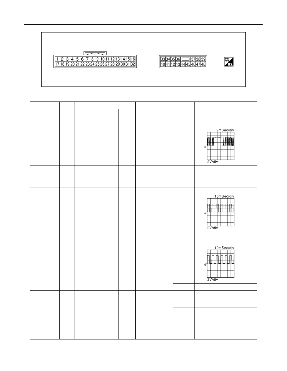
TERMINAL LAYOUT
PHYSICAL VALUES
JMJIA0199ZZ
Terminal No.
Wire
color
Description
Condition
Voltage (V)
(Approx)
+
-
Signal name
Input/
Output
1
Ground
L/W
UART communication
(RX)
Input
Ignition switch ON
3
—
R/Y
CAN-H
—
—
—
8
*1
Ground
LG
Parking brake switch
signal
Input
Parking brake
Applied
0
Release
Battery voltage
9
Ground
W/G
Reclining sensor sig-
nal
Input
Seat reclining
Operate
Stop
0 or 5
10
Ground
P/B
Lifting sensor (rear)
signal
Input
Seat lifting (rear)
Operate
Stop
0 or 5
11
Ground
BR
Sliding switch back-
ward signal
Input
Sliding switch
Operate
(back-
ward)
0
Release
Battery voltage
12
Ground
SB
Reclining switch back-
ward signal
Input
Reclining switch
Operate
(back-
ward)
0
Release
Battery voltage
JMJIA0118ZZ
JMJIA0119ZZ
JMJIA0119ZZ