Infiniti G35 (V35). Manual - part 749
 

  Index      Infiniti     Infiniti G35 (V35) Coupe - service repair manual 2007 year


Search            


Content   ..  747  748  749  750   ..


Infiniti G35 (V35). Manual - part 749


SE-98

POWER SEAT

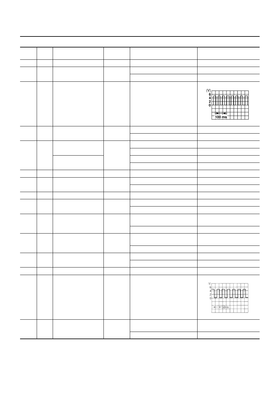
Terminal and Reference Value for Driver Side Seat Control Unit

NIS000HV

*: When operation condition is satisfied.

Termi-

nal

Wire 

color

Item

Signal

Input/Output

Condition

Voltage (V)

(Approx.)

1

R

BAT power supply

Input

—

Battery voltage

2*

L

Seatback switch signal 

Input

When seatback switch forward

0

Other than above

5

3*

R

Sliding sensor signal 

Input

When sliding motor operates


4

G

Power walk-in switch 
signal

Input

When power walk-in switch: ON 

0

Other than above

5

5

L/Y

A/T shift liver P position 
signal (with A/T models)

Input

When shift lever P position

0

Other than above

5

Parking brake signal
(with M/T models)

When pull the parking brake

0

Other than above

5

6

B

Ground

—

—

0

7

Y

Forward sliding switch 
signal

Input

Forward sliding switch: ON

0

Other than above

Battery voltage

8

R/W

BAT power supply

Input

—

Battery voltage

9

BR

Backward sliding switch 
signal

Input

Backward sliding switch: ON

0

Other than above

Battery voltage

10

W

Sliding motor forward 
signal

Output

When sliding motor forward 
operates

Battery voltage

Other than above

0

11

L

Sliding motor backward 
signal

Output

When sliding motor backward 
operates

Battery voltage

Other than above

0

13*

OR

Limit switch (forward)

Input

The seat slide front most part

0

Other than above

5

14

GY

Sliding sensor ground

—

—

0

15*

B/R

Vehicle speed signal 
(2-pulse)

Input

Speedometer operated 
[When vehicle speed is approx. 
40 km/h (25 MPH)]

16

G/W

Door switch and
seat belt switch signal 

Input

When seat belt is unfastened and 
door is open

0

Other than above

Battery voltage

PIIA4079E

ELF1080D

POWER SEAT

SE-99

C

D

E

F

G

H

J

K

L

M

A

B

SE

Terminal and Reference Value for Passenger Side Seat Control Unit

NIS000HW

*: When operation condition is satisfied.

Termi-

nal

Wire 

color

Item

Signal

Input/Output

Condition

Voltage (V)

(Approx.)

1

R

BAT power supply

Input

—

Battery voltage

2*

—

Seatback switch signal 

Input

When seatback switch forward

0

Other than above

5

3*

R

Sliding sensor signal 

Input

When sliding motor operates


4

—

Power walk-in switch 
signal

Input

When power walk-in switch: ON

0

Other than above

5

5

W

Seat belt buckle switch

Input

When passenger side seat belt is 
fastened 

5

Other than above

0

6

B

Ground

—

—

0

7

Y

Forward sliding switch 
signal

Input

Forward sliding switch: ON

0

Other than above

Battery voltage

8

R/W

BAT power supply

Input

— 

Battery voltage

9

BR

Backward sliding switch 
signal

Input

Backward sliding switch: ON

0

Other than above

Battery voltage

10

W

Sliding motor forward 
signal

Output

When sliding motor forward 
operates

Battery voltage

Other than above

0

11

L

Sliding motor backward 
signal

Output

When sliding motor backward 
operates

Battery voltage

Other than above

0

13*

OR

Limit switch (forward)

Input

The seat slide front most part

0

Other than above

5

14

GY

Sliding sensor ground

—

—

0

15*

B/R

Vehicle speed signal 
(2-pulse)

Input

Speedometer operated 
[When vehicle speed is approx. 
40 km/h (25 MPH)]

16

R/W

Passenger side door 
switch signal 

Input

Open passenger side door (ON)

0

Close passenger side door (OFF)

Battery voltage

PIIA4079E

ELF1080D

SE-100

POWER SEAT

Work Flow

NIS000HX

1.

Check the symptom and customer's requests.

2.

Understand the outline of system. Refer to 

SE-85, "System Description"

 .

3.

According to the trouble diagnosis chart, repair or replace the cause of the malfunction. Refer to 

SE-100,

"Symptom Chart"

 .

4.

Does power seat system operate normally? If Yes, GO TO 5, If No, GO TO 3.

5.

INSPECTION END.

Symptom Chart

NIS000HY

●

Check that other systems using the signal of the following systems operate normally.

Symptom

Diagnoses / service procedure

Refer to page

Driver side power seat cannot be operated.

1. Check driver seat control unit power supply and ground circuit.

SE-102

2. Check sliding switch. (driver side)

SE-104

3. Check sliding motor.

SE-106

4. Check reclining motor (driver side)

SE-108

5. Check lifting motor (front)

SE-112

6. Check lifting motor (rear)

SE-111

Passenger side power seat cannot be operated.

1.Check BCM power supply and ground circuit.

SE-101

2. Check passenger seat control unit power supply and ground 
circuit.

SE-102

3. Check sliding switch. (passenger side)

SE-105

4. Check sliding motor.

SE-106

5. Check reclining motor (passenger side)

SE-109

Power walk-in system does not operated, but 
power seat can be operated (drive side)

1. Check door switch and seat belt buckle switch. 

SE-116

2. Check A/T shift lever P position signal (with A/T models)

SE-119

2. Check parking brake signal (with M/T models)

SE-121

3. Check vehicle speed signal.

SE-122

4. Check sliding limit switch signal

SE-123

5. Check seatback switch signal

SE-124

6. Check power walk-in switch signal

SE-125

7. Check sliding sensor.

SE-107

Power walk-in system does not operated, but 
power seat can be operated (passenger side)

1. Check passenger side door switch. 

SE-113

2. Check passenger side seat belt buckle switch. 

SE-114

3. Check vehicle speed signal.

SE-122

4. Check sliding limit switch signal

SE-123

5. Check seatback switch signal

SE-124

6. Check power walk-in switch signal

SE-125

7. Check sliding sensor.

SE-107

POWER SEAT

SE-101

C

D

E

F

G

H

J

K

L

M

A

B

SE

Check BCM Power Supply and Ground Circuit 

NIS000HZ

1. 

FUSE INSPECTION

●

Check 10A fuse [No.18, located in the fuse block (J/B)]

●

Check 50A fusible link (letter F  located in the fuse and fusible link box).

NOTE:
Refer to 

RF-10, "Component Parts and Harness Connector Location"

 .

OK or NG

OK

>> GO TO 2.

NG

>> If fuse is blown out, be sure to eliminate cause of malfunction before installing new fuse. Refer to

PG-3, "POWER SUPPLY ROUTING CIRCUIT"

 .

2. 

CHECK POWER SUPPLY CIRCUIT

1.

Turn ignition switch OFF.

2.

Disconnect BCM connector.

3.

Check voltage between BCM connector M2 terminals 42, 55 and
ground.

OK or NG

OK

>> GO TO 3.

NG

>> Check BCM power supply circuit for open or short.

3. 

CHECK GROUND CIRCUIT

Check continuity between BCM connector M2 terminal 52 and
ground.

OK or NG

OK

>> Power supply and ground circuit is OK.

NG

>> Check BCM ground circuit for open.

42 (GY) – Ground

: Battery voltage

55 (W/R) – Ground

: Battery voltage

PIIB0134E

52 (B) – Ground

: Continuity should exist.

PIIA9131E


Content   ..  747  748  749  750   ..