Infiniti G35 (V35). Manual - part 311
 

  Index      Infiniti     Infiniti G35 (V35) Coupe - service repair manual 2007 year


Search            


Content   ..  309  310  311  312   ..


Infiniti G35 (V35). Manual - part 311


TROUBLE DIAGNOSIS

EC-125

C

D

E

F

G

H

I

J

K

L

M

A

EC

*: This item is the same as that of 1st trip freeze frame data.

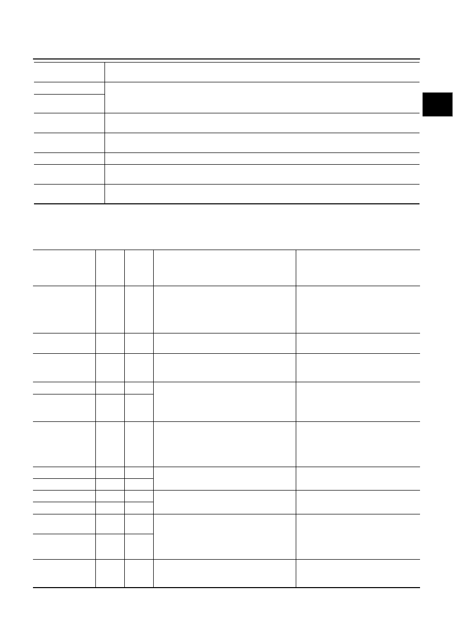
DATA MONITOR MODE
Monitored Item

×

: Applicable

S-FUEL TRM-B1 [%]

●

“Short-term fuel trim” at the moment a malfunction is detected is displayed.

●

The short-term fuel trim indicates dynamic or instantaneous feedback compensation to the base fuel 
schedule.

S-FUEL TRM-B2 [%]

ENGINE SPEED 
[rpm]

●

The engine speed at the moment a malfunction is detected is displayed.

VEHICL SPEED
[km/h] or [mph]

●

The vehicle speed at the moment a malfunction is detected is displayed.

ABSOL TH-P/S [%]

●

The throttle valve operating angle at the moment a malfunction is detected is displayed.

B/FUEL SCHDL 
[msec]

●

The base fuel schedule at the moment a malfunction is detected is displayed.

INT/A TEMP SE
[

°

C] or [

°

F]

●

The intake air temperature at the moment a malfunction is detected is displayed.

Freeze frame data 

item*

Description

Monitored item 

[Unit]

ECM 

INPUT 

SIG-

NALS

MAIN 

SIG-

NALS

Description

Remarks

ENG SPEED [rpm]

×

×

●

Indicates the engine speed computed from 
the signals of the crankshaft position sensor 
(POS) and camshaft position sensor 
(PHASE).

●

Accuracy becomes poor if engine 
speed drops below the idle rpm.

●

If the signal is interrupted while the 
engine is running, an abnormal value 
may be indicated.

MAS A/F SE-B1 [V]

×

×

●

The signal voltage of the mass air flow sensor 
is displayed.

●

When the engine is stopped, a certain 
value is indicated.

B/FUEL SCHDL 
[msec]

×

●

“Base fuel schedule” indicates the fuel injec-
tion pulse width programmed into ECM, prior 
to any learned on board correction.

A/F ALPHA-B1 [%]

×

●

The mean value of the air-fuel ratio feedback 
correction factor per cycle is indicated.

●

When the engine is stopped, a certain 
value is indicated.

●

This data also includes the data for the 
air-fuel ratio learning control.

A/F ALPHA-B2 [%]

×

COOLAN TEMP/S 
[

°

C] or [

°

F]

×

×

●

The engine coolant temperature (determined 
by the signal voltage of the engine coolant 
temperature sensor) is displayed.

●

When the engine coolant temperature 
sensor is open or short-circuited, ECM 
enters fail-safe mode. The engine cool-
ant temperature determined by the 
ECM is displayed.

A/F SEN1 (B1) [V]

×

×

●

The A/F signal computed from the input sig-
nal of the A/F sensor 1 is displayed.

A/F SEN1 (B2) [V]

×

HO2S2 (B1) [V]

×

●

The signal voltage of the heated oxygen sen-
sor 2 is displayed.

HO2S2 (B2) [V]

×

HO2S2 MNTR(B1) 
[RICH/LEAN]

×

●

Display of heated oxygen sensor 2 signal:
RICH: Means the amount of oxygen after 
three way catalyst is relatively small.
LEAN: Means the amount of oxygen after 
three way catalyst is relatively large.

●

When the engine is stopped, a certain 
value is indicated.

HO2S2 MNTR(B2) 
[RICH/LEAN]

×

VHCL SPEED SE 
[km/h] or [mph]

×

×

●

The vehicle speed computed from the vehicle 
speed signal sent from combination meter is 
displayed.

EC-126

TROUBLE DIAGNOSIS

BATTERY VOLT 
[V]

×

×

●

The power supply voltage of ECM is dis-
played.

ACCEL SEN 1 [V]

×

×

●

The accelerator pedal position sensor signal 
voltage is displayed.

●

ACCEL SEN 2 signal is converted by 
ECM internally. Thus, it differs from 
ECM terminal voltage signal.

ACCEL SEN 2 [V]

×

THRTL SEN 1 [V]

×

×

●

The throttle position sensor signal voltage is 
displayed.

●

THRTL SEN 2 signal is converted by 
ECM internally. Thus, it differs from 
ECM terminal voltage signal.

THRTL SEN 2 [V]

×

FUEL T/TMP SE 
[

°

C] or [

°

F]

×

●

The fuel temperature (determined by the sig-
nal voltage of the fuel tank temperature sen-
sor) is displayed.

INT/A TEMP SE 
[

°

C] or [

°

F]

×

×

●

The intake air temperature (determined by 
the signal voltage of the intake air tempera-
ture sensor) is indicated.

EVAP SYS PRES 
[V]

×

●

The signal voltage of EVAP control system 
pressure sensor is displayed.

FUEL LEVEL SE 
[V]

×

●

The signal voltage of the fuel level sensor is 
displayed.

START SIGNAL 
[ON/OFF]

×

×

●

Indicates start signal status [ON/OFF] com-
puted by the ECM according to the signals of 
engine speed and battery voltage.

●

After starting the engine, [OFF] is dis-
played regardless of the starter signal.

CLSD THL POS 
[ON/OFF]

×

×

●

Indicates idle position [ON/OFF] computed by 
ECM according to the accelerator pedal posi-
tion sensor signal.

AIR COND SIG 
[ON/OFF]

×

×

●

Indicates [ON/OFF] condition of the air condi-
tioner switch as determined by the air condi-
tioner signal.

P/N POSI SW
[ON/OFF]

×

×

●

Indicates [ON/OFF] condition from the park/
neutral position (PNP) switch signal.

PW/ST SIGNAL 
[ON/OFF]

×

×

●

[ON/OFF] condition of the power steering 
system (determined by the signal voltage of 
the power steering pressure sensor) is indi-
cated.

LOAD SIGNAL 
[ON/OFF]

×

×

●

Indicates [ON/OFF] condition from the electri-
cal load signal.
ON: Rear window defogger switch is ON and/
or lighting switch is in 2nd position.
OFF: Both rear window defogger switch and 
lighting switch are OFF.

IGNITION SW
[ON/OFF]

×

●

Indicates [ON/OFF] condition from ignition 
switch signal.

HEATER FAN SW
[ON/OFF]

×

●

Indicates [ON/OFF] condition from the heater 
fan switch signal.

BRAKE SW
[ON/OFF]

×

●

Indicates [ON/OFF] condition from the stop 
lamp switch signal.

INJ PULSE-B1 
[msec]

×

●

Indicates the actual fuel injection pulse width 
compensated by ECM according to the input 
signals.

●

When the engine is stopped, a certain 
computed value is indicated.

INJ PULSE-B2 
[msec]

IGN TIMING 
[BTDC]

×

●

Indicates the ignition timing computed by 
ECM according to the input signals.

●

When the engine is stopped, a certain 
value is indicated.

Monitored item 

[Unit]

ECM 

INPUT 

SIG-

NALS

MAIN 

SIG-

NALS

Description

Remarks

TROUBLE DIAGNOSIS

EC-127

C

D

E

F

G

H

I

J

K

L

M

A

EC

CAL/LD VALUE [%]

●

“Calculated load value” indicates the value of 
the current air flow divided by peak air flow.

MASS AIRFLOW 
[g·m/s]

●

Indicates the mass air flow computed by ECM 
according to the signal voltage of the mass air 
flow sensor.

PURG VOL C/V 
[%]

●

Indicates the EVAP canister purge volume 
control solenoid valve control value computed 
by the ECM according to the input signals.

●

The opening becomes larger as the value 
increases.

INT/V TIM(B1) 
[

°

CA]

●

Indicates [

°

CA] of intake camshaft advanced 

angle. 

INT/V TIM(B2) 
[

°

CA]

EXH/V TIM B1*  
[

°

CA]

●

Indicates [

°

CA] of exhaust camshaft retarded 

angle. 

EXH/V TIM B2* 
[

°

CA]

INT/V SOL(B1) [%]

●

The control value of the intake valve timing 
control solenoid valve (determined by ECM 
according to the input signals) is indicated.

●

The advance angle becomes larger as the 
value increases.

INT/V SOL(B2) [%]

EX VTC DTY B1* 
[%]

●

The control value of the exhaust valve timing 
control magnet retarder (determined by ECM 
according to the input signals) is indicated.

●

The retard angle becomes larger as the value 
increases.

EX VTC DTY B2* 
[%]

AIR COND RLY 
[ON/OFF]

×

●

The air conditioner relay control condition 
(determined by ECM according to the input 
signals) is indicated.

FUEL PUMP RLY 
[ON/OFF]

×

●

Indicates the fuel pump relay control condi-
tion determined by ECM according to the 
input signals.

VENT CONT/V 
[ON/OFF]

●

The control condition of the EVAP canister 
vent control valve (determined by ECM 
according to the input signals) is indicated.
ON: Closed
OFF: Open

THRTL RELAY 
[ON/OFF]

×

●

Indicates the throttle control motor relay con-
trol condition determined by the ECM accord-
ing to the input signals.

COOLING FAN
[HI/LOW/OFF]

×

●

The control condition of the cooling fan 
(determined by ECM according to the input 
signals) is indicated.
HI: High speed operation
LOW: Low speed operation
OFF: Stop

HO2S2 HTR (B1) 
[ON/OFF]

●

Indicates [ON/OFF] condition of heated oxy-
gen sensor 2 heater determined by ECM 
according to the input signals.

HO2S2 HTR (B2) 
[ON/OFF]

Monitored item 

[Unit]

ECM 

INPUT 

SIG-

NALS

MAIN 

SIG-

NALS

Description

Remarks

EC-128

TROUBLE DIAGNOSIS

I/P PULLY SPD
[rpm]

●

Indicates the engine speed computed from 
the turbine revolution sensor signal.

VEHICLE SPEED
[km/h] or [mph]

●

Indicates the vehicle speed computed from 
the revolution sensor signal.

IDL A/V LEARN 
[YET/CMPLT]

●

Display the condition of Idle Air Volume 
Learning
YET: Idle Air Volume Learning has not been 
performed yet.
CMPLT: Idle Air Volume Learning has already 
been performed successfully.

TRVL AFTER MIL 
[km] or [mile]

●

Distance traveled while MIL is activated.

ENG OIL TEMP* 
[

°

C] or [

°

F]

●

The engine oil temperature (determined by 
the signal voltage of the engine oil tempera-
ture sensor) is displayed.

●

This sensor is not for controlling the 
engine system, nor for the on board 
diagnosis.

A/F S1 HTR(B1) 
[%]

●

Indicates A/F sensor 1 heater control value 
computed by ECM according to the input sig-
nals.

●

The current flow to the heater becomes larger 
as the value increases.

A/F S1 HTR(B2) 
[%]

AC PRESS SEN 
[V]

●

The signal voltage from the refrigerant pres-
sure sensor is displayed.

VHCL SPEED SE 
[km/h] or [mph]

●

The vehicle speed computed from the vehicle 
speed signal sent from TCM is displayed.

SET VHCL SPD
[km/h] or [mph]

●

The preset vehicle speed is displayed.

MAIN SW
[ON/OFF]

●

Indicates [ON/OFF] condition from MAIN 
switch signal.

CANCEL SW
[ON/OFF]

●

Indicates [ON/OFF] condition from CANCEL 
switch signal.

RESUME/ACC SW
[ON/OFF]

●

Indicates [ON/OFF] condition from RESUME/
ACCELERATE switch signal.

SET SW
[ON/OFF]

●

Indicates [ON/OFF] condition from SET/
COAST switch signal.

BRAKE SW1
[ON/OFF]

●

Indicates [ON/OFF] condition from ASCD 
brake switch signal and ASCD clutch switch 
signal (M/T)

BRAKE SW2
[ON/OFF]

●

Indicates [ON/OFF] condition of stop lamp 
switch signal.

VHCL SPD CUT
[NON/CUT]

●

Indicates the vehicle cruise condition.
NON: Vehicle speed is maintained at the 
ASCD set speed.
CUT: Vehicle speed increased to excessively 
high compared with the ASCD set speed, and 
ASCD operation is cut off.

LO SPEED CUT
[NON/CUT]

●

Indicates the vehicle cruise condition.
NON: Vehicle speed is maintained at the 
ASCD set speed.
CUT: Vehicle speed decreased to excessively 
low compared with the ASCD set speed, and 
ASCD operation is cut off.

Monitored item 

[Unit]

ECM 

INPUT 

SIG-

NALS

MAIN 

SIG-

NALS

Description

Remarks


Content   ..  309  310  311  312   ..