Infiniti G35 (V35). Manual - part 146


  Index      Infiniti     Infiniti G35 (V35) Coupe - service repair manual 2007 year


Search            


Content   ..  144  145  146  147   ..


Infiniti G35 (V35). Manual - part 146


TELEPHONE

AV-99

C

D

E

F

G

H

I

J

L

M

A

B

AV

TKWM3521E
AV-100

TELEPHONE

TKWM3522E

TELEPHONE

AV-101

C

D

E

F

G

H

I

J

L

M

A

B

AV

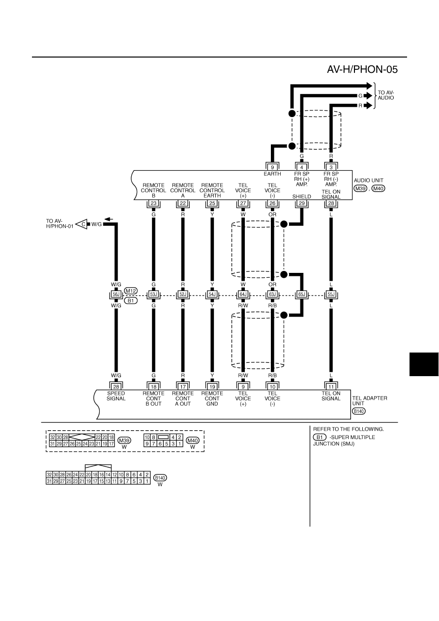
Terminals and Reference Value for TEL Adapter Unit

NKS002GW

Terminal

 (Wire color)

Item

Signal 

input/out-

put

Condition

Reference value

+

–

Ignition 

switch

Operation

1

(GY)

Ground

Battery power 
supply

Input

OFF

—

Battery voltage

2

(LG)

Ground

ACC power sup-
ply

Input

ACC

—

Battery voltage

3

(Y/R)

Ground

Ignition signal

Input

ON

—

Battery voltage

4

(B)

Ground

Ground

—

ON

—

Approx. 0 V

6

—

Shield

—

—

—

—

7

(R)

8

(B)

MIC. signal

Input

ON

Uttering in front of 
the microphone 
while using the 
hands-free phone 
system.

9

(R/W)

10

(R/B)

TEL voice signal

Output

ON

Receiving the 
party's voice while 
using the hands-
free phone system.

11

(L)

Ground

TEL ON signal

Output

ON

While using hands-
free phone system.

Approx. 0 V

While not using 
handsfree phone 
system.

Approx. 5 V

12

(R)

Ground

Remote control A

Input

ON

Press  

switch

Approx. 0 V

Press SEEK UP 
switch

Approx. 1.7 V

Press VOL UP 
switch

Approx. 3.3 V

Except for above

Approx. 5 V

13

(G)

Ground

Remote control B

Input

ON

Press  

switch

Approx. 0 V

Press SEEK DOWN 
switch

Approx. 1.7 V

Press VOL DOWN 
switch

Approx. 3.3 V

Except for above

Approx. 5 V

14

(Y)

Ground

Remote control 
ground

—

ON

—

Approx. 0 V

SKIB3609E

SKIB3609E

AV-102

TELEPHONE

Terminals and Reference Value for Audio Unit for BOSE System

NKS002GX

Refer to 

AV-22, "Terminals and Reference Value for Audio Unit for BOSE System"

 .

Steering Wheel Audio Control Switch Resistance Inspection

NKS002GY

Refer to 

AV-26, "Steering Wheel Audio Control Switch Resistance Inspection"

 .

Self-Diagnosis Function

NKS002QB

The followings are diagnosis functions performed by TEL adapter unit.

●

Performs the unit self

−

diagnosis and antenna diagnosis, and informs results with the indicator and voice

guidance.

●

Informs vehicle speed pulse count from the time of key switch ON with voice guidance, and enables to
check vehicle speed signal.

●

Outputs voice giving to microphone with speaker, and enables to check microphone function.

15

(Y/G)

Ground

Indicator signal

Output

ON

Microphone indica-
tor ON, and lighting 
switch OFF

Approx. 1.3 V

Microphone indica-
tor ON, and lighting 
switch ON

Approx. 0.8 V

Microphone unit 
indicator OFF

Approx. 12 V

17

(R)

Ground

Remote control A

Output

ON

Press  

switch

Approx. 0 V

Press SEEK UP 
switch

Approx. 1.7 V

Press VOL UP 
switch

Approx. 3.3 V

Except for above

Approx. 5 V

18

(G)

Ground

Remote control B

Output

ON

Press  

switch

Approx. 0 V

Press SEEK DOWN 
switch

Approx. 1.7 V

Press VOL DOWN 
switch

Approx. 3.3 V

Except for above

Approx. 5 V

19

(Y)

Ground

Remote control 
ground

—

ON

—

Approx. 0 V

22

(B)

Ground

Ground

—

ON

—

Approx. 0 V

28

(W/G)

Ground

Vehicle 
speed signal
(8-pulse)

Input

ON

When vehicle speed 
is approx. 40 km/h 
(25 MPH)

29

(W)

Ground

MIC. VCC 

Output

ON

—

Approx. 5 V

41 —

TEL 

signal

—

—

—

—

Terminal

 (Wire color)

Item

Signal 

input/out-

put

Condition

Reference value

+

–

Ignition 

switch

Operation

SKIA6649J


Content   ..  144  145  146  147   ..