Infiniti G35 (V35). Manual - part 81
 

  Index      Infiniti     Infiniti G35 (V35) Coupe - service repair manual 2007 year


Search            


Content   ..  79  80  81  82   ..


Infiniti G35 (V35). Manual - part 81


ASSEMBLY

AT-315

D

E

F

G

H

I

J

K

L

M

A

B

AT

d.

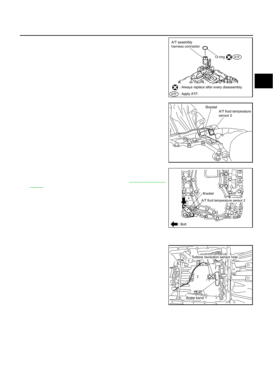
Install O-ring to A/T assembly harness connector.

CAUTION:

●

Do not reuse O-ring.

●

Apply ATF to O-ring.

e.

Install A/T fluid temperature sensor 2 to bracket.

f.

Install A/T fluid temperature sensor 2 (with bracket) in control
valve with TCM, and then tighten A/T fluid temperature sensor 2
mounting bolt to the specified torque. Refer to 

AT-255, "Compo-

nents"

CAUTION:

Adjust bolt hole of bracket to bolt hole of control valve.

g.

Install control valve with TCM in transmission case.

CAUTION:

●

Make sure that turbine revolution sensor securely installs
turbine revolution sensor hole.

●

Hang down revolution sensor harness toward outside so
as not to disturb installation of control valve with TCM.

●

Adjust A/T assembly harness connector of control valve
with TCM to terminal hole of transmission case.

SCIA5155E

SCIA5264E

SCIA5301E

SCIA5034E

AT-316

ASSEMBLY

●

Assemble it so that manual valve cutout is engaged with
manual plate projection.

h.

Install bolts A, B and C to control valve with TCM.

●

: Front

i.

Tighten bolt 1, 2 and 3 temporarily to prevent dislocation. After
that tighten them in order (1 

→

 2 

→

 3), and then tighten other

bolts to the specified torque. Refer to 

AT-255, "Components"

 .

●

: Front

10. Connect A/T fluid temperature sensor 2 connector (A).
11. Securely fasten terminal cord assembly and A/T fluid tempera-

ture sensor 2 harness with terminal clips.

●

: Terminal clip (4)

12. Connect revolution sensor connector.

SCIA5035E

Bolt symbol

Length mm (in)

Number of bolts

A

42 (1.65)

5

B

55 (2.17)

6

C

40 (1.57)

1

SCIA8077E

SCIA8078E

SCIA8124E

SCIA7524E

ASSEMBLY

AT-317

D

E

F

G

H

I

J

K

L

M

A

B

AT

13. Securely fasten revolution sensor harness with terminal clip.

14. Pull down A/T assembly harness connector.

CAUTION:

Be careful not to damage connector.

15. Install snap ring to A/T assembly harness connector.

16. Install magnets in oil pan.

17. Install oil pan to transmission case.

a.

Install oil pan gasket to transmission case.

CAUTION:

●

Do not reuse oil pan gasket.

●

Install it in the direction to align hole positions.

●

Complete remove all moisture, oil and old gasket, etc. from oil pan gasket mounting surface.

SCIA7526E

SCIA5299E

SCIA5300E

SCIA5200E

AT-318

ASSEMBLY

b.

Install oil pan (2) and clips (1) to transmission case.

CAUTION:

●

Install it so that drain plug (3) comes to the position as
shown in the figure.

●

Be careful not to pinch harnesses.

●

Complete remove all moisture, oil and old gasket, etc.
from oil pan mounting surface.

c.

Tighten oil pan mounting bolts to the specified torque in numeri-
cal order shown in the figure after temporarily tightening them.
Refer 

AT-255, "Components"

 .

CAUTION:

Do not reuse oil pan mounting bolts.

18. Install drain plug to oil pan, and then tighten drain plug to the

specified torque. Refer to 

AT-255, "Components"

 .

CAUTION:

Do not reuse drain plug gasket.

19. Install torque converter.

a.

Pour ATF into torque converter.

●

Approximately 2 liter (2-1/8 US qt, 1-3/4 Imp qt) of ATF is
required for a new torque converter.

●

When reusing old torque converter, add the same amount
of ATF as was drained.

b.

Install torque converter while aligning notches of torque con-
verter with notches of oil pump.

CAUTION:

Install torque converter while rotating it.

c.

Measure distance “A” to check that torque converter is in proper
position.

SCIA8117E

SCIA4113E

SAT428DA

SCIA5010E

Distance “A”:

25.0 mm (0.98 in) or more

SAT017B


Content   ..  79  80  81  82   ..