Infiniti G35 (V35). Manual - part 68
 

  Index      Infiniti     Infiniti G35 (V35) Coupe - service repair manual 2007 year


Search            


Content   ..  66  67  68  69   ..


Infiniti G35 (V35). Manual - part 68


DISASSEMBLY

AT-263

D

E

F

G

H

I

J

K

L

M

A

B

AT

DISASSEMBLY

PFP:31020

Disassembly

NCS000J4

CAUTION:

Do not disassemble parts behind Drum Support. Refer to 

AT-17, "Cross-sectional View"

 .

1.

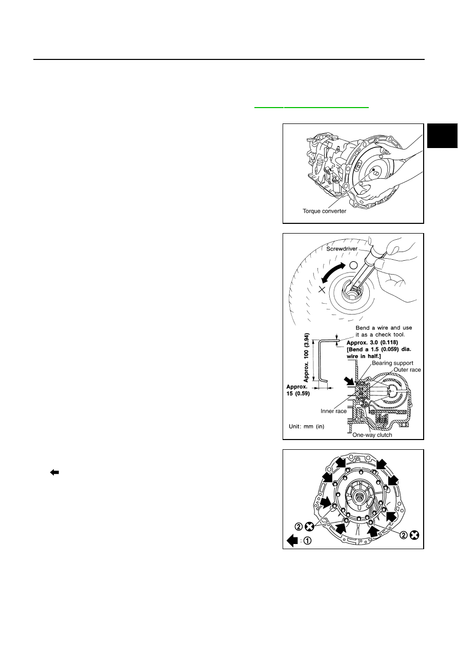
Drain ATF through drain plug.

2.

Remove torque converter by holding it firmly and turing while
pulling straight out.

3.

Check torque converter one-way clutch using check tool as
shown at figure.

a.

Insert check tool into the groove of bearing support built into
one-way clutch outer race.

b.

When fixing bearing support with check tool, rotate one-way
clutch spline using screwdriver.

c.

Check that inner race rotates clockwise only. If not, replace
torque converter assembly.

4.

Remove tightening bolts (1) for converter housing and transmis-
sion case.

●

: Bolt (8)

●

Self-sealing bolts (2)

5.

Remove converter housing from transmission case.

CAUTION:

Be careful not to scratch converter housing.

SCIA5010E

SCIA3171E

SCIA8029E

AT-264

DISASSEMBLY

6.

Remove O-ring from input clutch assembly.

7.

Remove tightening bolts for oil pump assembly and transmis-
sion case.

8.

Attach the sliding hammers to oil pump assembly and extract it
evenly from transmission case.

CAUTION:

●

Fully tighten sliding hammer screw.

●

Make sure that bearing race is installed to the oil pump
assembly edge surface.

9.

Remove O-ring from oil pump assembly.

SCIA5011E

SCIA2300E

SCIA5312E

SCIA5172E

DISASSEMBLY

AT-265

D

E

F

G

H

I

J

K

L

M

A

B

AT

10. Remove bearing race from oil pump assembly.

11. Remove needle bearing from front sun gear.

12. Remove front sun gear assembly from front carrier assembly.

NOTE:
Remove front sun gear by rotating left/right.

13. Remove seal rings from input clutch assembly.

14. Remove front carrier assembly from rear carrier assembly. (With

input clutch assembly and rear internal gear.)

CAUTION:

Be careful to remove it with needle bearing.

SCIA6529E

SCIA2808E

SCIA5014E

SCIA2470E

SCIA5015E

AT-266

DISASSEMBLY

15. Loosen lock nut and remove band servo anchor end pin from

transmission case.

16. Remove brake band from transmission case.

●

To prevent brake linings from cracking or peeling, do not
stretch the flexible band unnecessarily. When removing
the brake band, always secure it with a clip as shown in
the figure at right.
Leave the clip in position after removing the brake band.

●

Check brake band facing for damage, cracks, wear or
burns.

17. Remove mid carrier assembly and rear carrier assembly as a

unit.

18. Remove mid carrier assembly from rear carrier assembly.

SCIA6512E

SCIA2580E

SAT655

SCIA5017E

SCIA5697E


Content   ..  66  67  68  69   ..