Infiniti G35 (V35). Manual - part 23
 

  Index      Infiniti     Infiniti G35 (V35) Coupe - service repair manual 2007 year


Search            


Content   ..  21  22  23  24   ..


Infiniti G35 (V35). Manual - part 23


TROUBLE DIAGNOSIS

AT-83

D

E

F

G

H

I

J

K

L

M

A

B

AT

TCM Input/Output Signal Reference Values

NCS000C5

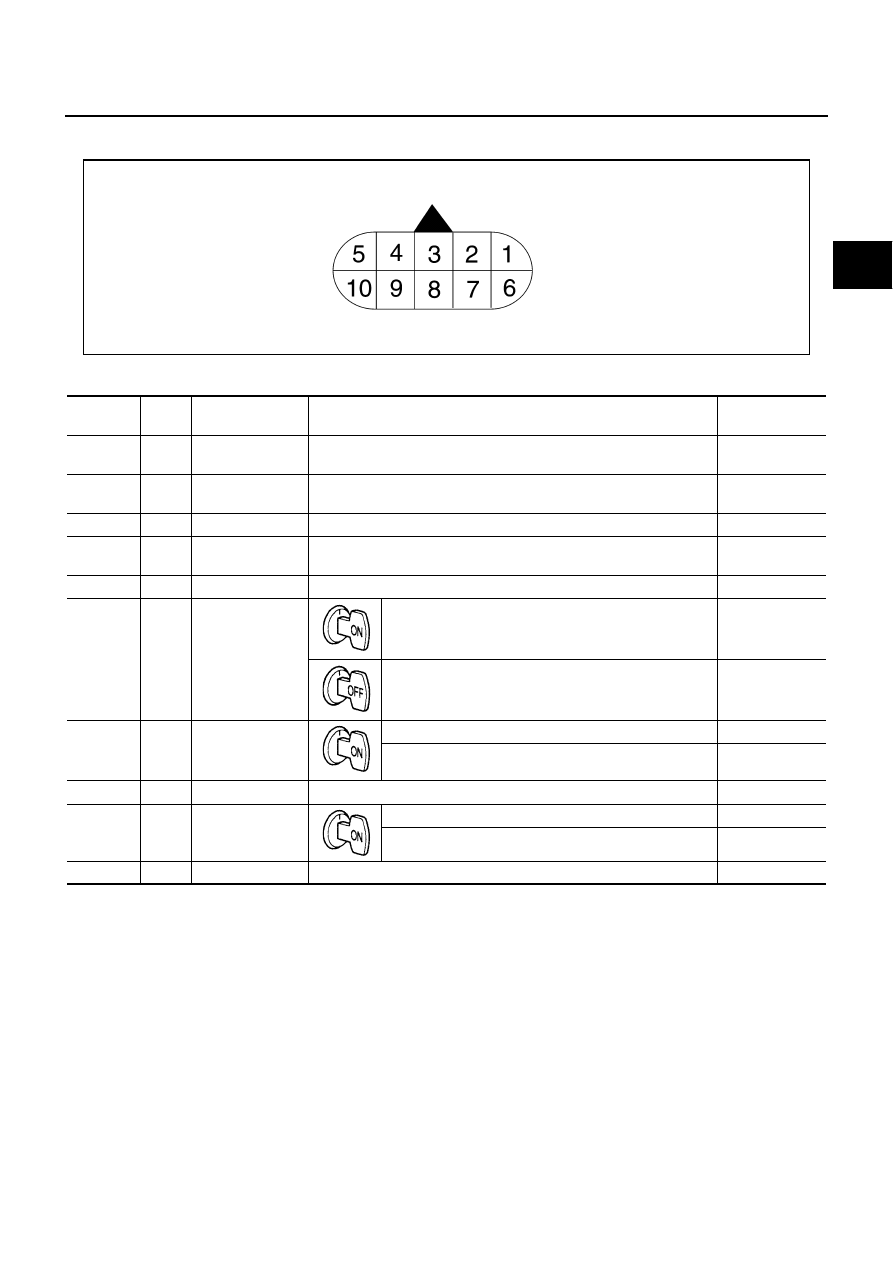
A/T ASSEMBLY HARNESS CONNECTOR TERMINAL LAYOUT 

TCM INSPECTION TABLE

Data are reference value and are measured between each terminal and ground.

SCIA1658E

Terminal

Wire 

color

Item

Condition

Data (Approx.)

1

R/W

Power supply
(Memory back-up)

Always

Battery voltage

2

R/W

Power supply
(Memory back-up)

Always

Battery voltage

3

L

CAN-H

–

–

4

PU

K-line (CONSULT-
II signal)

The terminal is connected to the data link connector for CONSULT-II.

–

5

B

Ground

Always

0 V

6

Y/R

Power supply

–

Battery voltage

–

0  V

7

R

Back-up lamp 
relay

Selector lever in “R” position.

0 V

Selector lever in other positions.

Battery voltage

8

P

CAN-L

–

–

9

GY/R

Starter  relay

Selector lever in “N” and “P” positions.

Battery voltage

Selector lever in other positions.

0 V

10

B

Ground

Always

0 V

AT-84

TROUBLE DIAGNOSIS

CONSULT-II Function (A/T)

NCS000C6

CONSULT-II can display each diagnostic item using the diagnostic test modes shown following.

FUNCTION

CONSULT-II REFERENCE VALUE

NOTICE:
1.

The CONSULT-II electrically displays shift timing and lock-up timing (that is, operation timing of each sole-
noid).
Check for time difference between actual shift timing and the CONSULT-II display. If the difference is
noticeable, mechanical parts (except solenoids, sensors, etc.) may be malfunctioning. Check mechanical
parts using applicable diagnostic procedures.

2.

Shift schedule (which implies gear position) displayed on CONSULT-II and that indicated in Service Man-
ual may differ slightly. This occurs because of the following reasons:

–

Actual shift schedule has more or less tolerance or allowance,

–

Shift schedule indicated in Service Manual refers to the point where shifts start, and

–

Gear position displayed on CONSULT-II indicates the point where shifts are completed.

3.

Display of solenoid valves on CONSULT-II changes at the start of shifting, while gear position is displayed
upon completion of shifting (which is computed by TCM).

Diagnostic test mode

Function

Reference page

Self-diagnostic results

Self-diagnostic results can be read and erased quickly.

AT-86

Data monitor

Input/Output data in the TCM can be read.

AT-89

CAN diagnostic support 
monitor

The results of transmit/receive diagnosis of CAN communication can be read.

AT-93

Function test

Conducted by CONSULT-II instead of a technician to determine whether each system 
is “OK” or “NG”.

—

DTC work support

Select the operating condition to confirm Diagnosis Trouble Codes.

AT-93

ECU part number

TCM part number can be read.

—

Item name

Condition 

Display value (Approx.)

ATF TEMP SE 1

0

°

C (32

°

F) - 20

°

C (68

°

F) - 80

°

C (176

°

F)

3.3 - 2.7 - 0.9 V

ATF TEMP SE 2

3.3 - 2.5 - 0.7 V

TCC SOLENOID

Slip lock-up is active

0.2 - 0.4 A

Lock-up is active

0.4 - 0.6 A

SLCT LVR POSI

Selector lever in “N” and “P” positions.

N/P

Selector lever in “R” position.

R

Selector lever in “D” position.

D

VHCL/S SE-A/T

During driving

Approximately matches the speed-
ometer reading.

ENGINE SPEED

Engine running

Closely matches the tachometer 
reading.

LINE PRES SOL

During driving

0.2 - 0.6 A

TURBINE REV

During driving (lock-up ON)

Approximately matches the engine 
speed.

VHCL/S SE-MTR

During driving

Approximately matches the speed-
ometer reading.

ATF PRES SW 1

Front brake engaged. Refer to 

AT-19


.

ON

Front brake disengaged. Refer to 

AT-19


.

OFF

ATF PRES SW 2

Low coast brake engaged. Refer to 

AT-19


.

ON

Low coast brake disengaged. Refer to 

AT-19


.

OFF

ATF PRES SW 3

Input clutch engaged. Refer to 

AT-19


.

ON

Input clutch disengaged. Refer to 

AT-19


.

OFF

TROUBLE DIAGNOSIS

AT-85

D

E

F

G

H

I

J

K

L

M

A

B

AT

ATF PRES SW 5

Direct clutch engaged. Refer to 

AT-19


.

ON

Direct clutch disengaged. Refer to 

AT-19


.

OFF

ATF PRES SW 6

High and low reverse clutch engaged. Refer to 

AT-19


.

ON

High and low reverse clutch disengaged. Refer to 

AT-19


.

OFF

I/C SOLENOID

Input clutch disengaged. Refer to 

AT-19

 .

0.6 - 0.8 A

Input clutch engaged. Refer to 

AT-19

 .

0 - 0.05 A

FR/B SOLENOID

Front brake engaged. Refer to 

AT-19

 .

0.6 - 0.8 A

Front brake disengaged. Refer to 

AT-19

 .

0 - 0.05 A

D/C SOLENOID

Direct clutch disengaged. Refer to 

AT-19

 .

0.6 - 0.8 A

Direct clutch engaged. Refer to 

AT-19

 .

0 - 0.05 A

HLR/C SOL

High and low reverse clutch disengaged. Refer to 

AT-19

 .

0.6 - 0.8 A

High and low reverse clutch engaged. Refer to 

AT-19

 .

0 - 0.05 A

ON OFF SOL

Low coast brake engaged. Refer to 

AT-19


.

ON

Low coast brake disengaged. Refer to 

AT-19


.

OFF

MANU MODE SW

Manual shift gate position (neutral)

ON

Other than the above

OFF

NON M-MODE SW

Manual shift gate position

OFF

Other than the above

ON

UP SW LEVER

Selector lever: + side

ON

Other than the above

OFF

DOWN SW LEVER

Selector lever: - side

ON

Other than the above

OFF

STARTER RELAY

Selector lever in “N” and “P” positions.

ON

Selector lever in other positions.

OFF

ACCELE POSI

Released accelerator pedal.

0.0/8

Fully depressed accelerator pedal.

8.0/8

CLSD THL POS

Released accelerator pedal.

ON

Fully depressed accelerator pedal.

OFF

W/O THL POS

Fully depressed accelerator pedal.

ON

Released accelerator pedal.

OFF

BRAKE SW

Depressed brake pedal.

ON

Released brake pedal.

OFF

GEAR

During driving

1, 2, 3, 4, 5

Item name

Condition 

Display value (Approx.)

AT-86

TROUBLE DIAGNOSIS

CONSULT-II SETTING PROCEDURE

Refer to 

GI-37, "CONSULT-II Start Procedure"

 .

SELF-DIAGNOSTIC RESULT MODE

After performing self-diagnosis, place check marks for results on the 

AT-45, "DIAGNOSTIC WORKSHEET"

 .

Reference pages are provided following the items.

Operation Procedure

1.

Touch “SELF-DIAG RESULTS” on “SELECT DIAG MODE”
screen.
Display shows malfunction experienced since the last erasing
operation.

Display Items List

X: Applicable, —: Not applicable

BCIA0031E

 Items (CONSULT-

II screen terms)

Malfunction is detected when...

TCM self-

diagnosis

OBD-II (DTC)

Reference 

page

 “A/T” with   

CONSULT-II

MIL

*1

 , 

“ENGINE” with 

CONSULT-II or 

GST

CAN COMM CIR-
CUIT

●

When TCM is not transmitting or receiving CAN communi-
cation signal for 2 seconds or more.

U1000

U1000

AT-98

STARTER RELAY/
CIRC

●

If this signal is ON other than in “P” or “N” position, this is 
judged to be a malfunction.
(And if it is OFF in “P” or “N” position, this too is judged to 
be a malfunction.)

P0615

—

AT-101

TCM

●

TCM is malfunctioning

P0700

P0700

AT-105

PNP SW/CIRC

●

PNP switch 1-4 signals input with impossible pattern

●

PNP switch 3 monitor terminal cut line

●

P position is detected from “N” position without any other 
position being detected in between.

P0705

P0705

AT-106

TURBINE REV S/
CIRC

●

TCM does not receive the proper voltage signal from the 
sensor.

●

TCM detects an irregularity only at position of 4th gear for 
turbine revolution sensor 2.

P0717

P0717

AT-110

VEH SPD SEN/
CIR AT

●

Signal from vehicle speed sensor A/T (Revolution sensor) 
not input due to cut line or the like

●

Unexpected signal input during running

●

After ignition switch is turned ON, unexpected signal input 
from vehicle speed sensor MTR before the vehicle starts 
moving

P0720

P0720

AT-112

ENGINE SPEED 
SIG

●

TCM does not receive the CAN communication signal 
from the ECM.

P0725

P0725

AT-117

TCC SOLENOID/
CIRC

●

Normal voltage not applied to solenoid due to cut line, 
short, or the like

P0740

P0740

AT-119

A/T TCC S/V 
FNCTN

●

A/T cannot perform lock-up even if electrical circuit is 
good.

●

TCM detects as irregular by comparing difference value 
with slip rotation.

P0744

P0744*2

AT-121


Content   ..  21  22  23  24   ..