Infiniti G20 (P11). Manual - part 513
Trouble Diagnoses: “AIR BAG” Warning Lamp
Does Not Turn Off
=NCRS0030
DIAGNOSTIC PROCEDURE 9
NCRS0030S01
1
SEE THE DEPLOYMENT OF AIR BAG MODULE
Is air bag module deployed?
Yes or No
Yes
©
Refer to COLLISION DIAGNOSIS (RS-60).
No
©
GO TO 2.
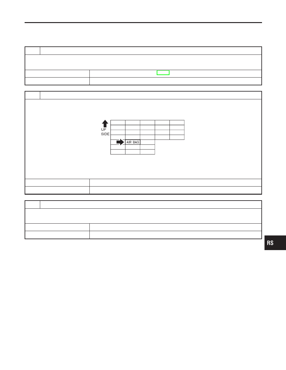
2
CHECK “AIR BAG” FUSE
Is SRS “Air Bag” fuse OK?
SRS577
OK or NG
OK
©
GO TO 4.
NG
©
GO TO 3.
3
CHECK “AIR BAG” FUSE AGAIN
Replace “AIR BAG” fuse and turn ignition switch ON.
Is “AIR BAG” fuse blown again?
Yes
©
Repair main harness and/or replace air bag harness.
No
©
INSPECTION END
GI
MA
EM
LC
EC
FE
CL
MT
AT
AX
SU
BR
ST
BT
HA
SC
EL
IDX
SUPPLEMENTAL RESTRAINT SYSTEM (SRS)
Trouble Diagnoses: “AIR BAG” Warning Lamp Does Not Turn Off
RS-57