Infiniti G20 (P11). Manual - part 424
THA251
GI
MA
EM
LC
EC
FE
CL
MT
AT
AX
SU
BR
ST
RS
BT
SC
EL
IDX
TROUBLE DIAGNOSES
AUTO
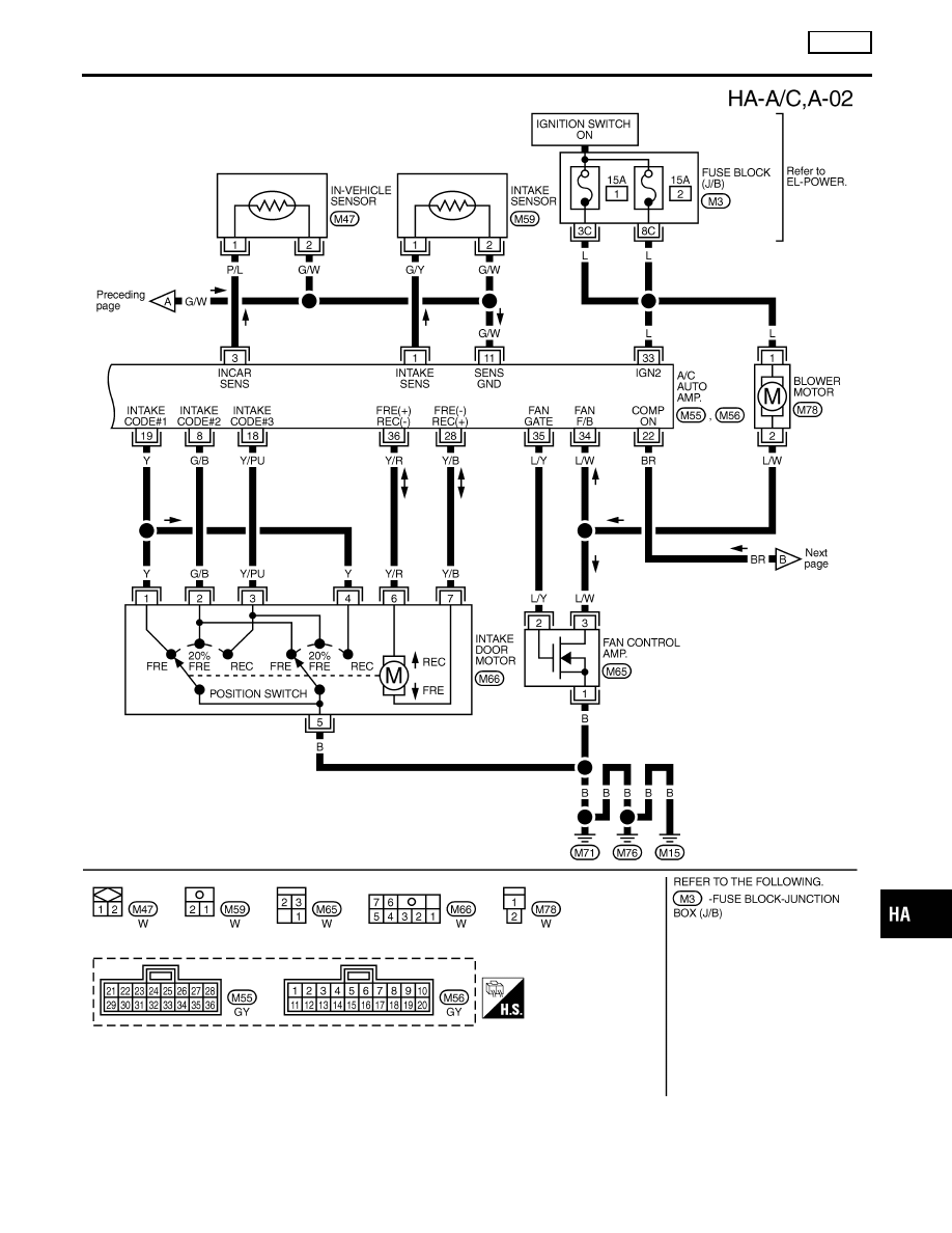
Wiring Diagram — A/C, A — (Cont’d)
HA-27
|
|
|
THA251 GI MA EM LC EC FE CL MT AT AX SU BR ST RS BT SC EL IDX TROUBLE DIAGNOSES AUTO Wiring Diagram — A/C, A — (Cont’d) HA-27 |