Infiniti G20 (P11). Manual - part 413
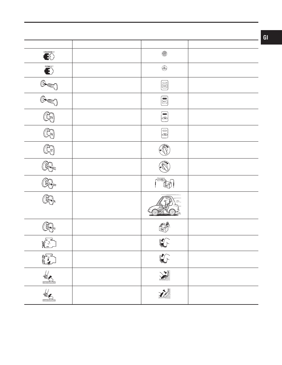
Key to Symbols Signifying Measurements or
Procedures
NCGI0006S02
Symbol
Symbol explanation
Symbol
Symbol explanation
Check after disconnecting the con-
nector to be measured.
Procedure with Generic Scan Tool
(GST, OBD-II scan tool)
Check after connecting the connector
to be measured.
Procedure without CONSULT-II or
GST
Insert key into ignition switch.
A/C switch is “OFF”.
Remove key from ignition switch.
A/C switch is “ON”.
Turn ignition switch to “OFF” position.
REC switch is “ON”.
Turn ignition switch to “ON” position.
REC switch is “OFF”.
Turn ignition switch to “START” posi-
tion.
Fan switch is “ON”. (At any position
except for “OFF” position)
Turn ignition switch from “OFF” to
“ACC” position.
Fan switch is “OFF”.
Turn ignition switch from “ACC” to
“OFF” position.
Apply positive voltage from battery
with fuse directly to components.
Turn ignition switch from “OFF” to
“ON” position.
Drive vehicle.
Turn ignition switch from “ON” to
“OFF” position.
Disconnect battery negative cable.
Do not start engine, or check with
engine stopped.
Depress brake pedal.
Start engine, or check with engine
running.
Release brake pedal.
Apply parking brake.
Depress accelerator pedal.
Release parking brake.
Release accelerator pedal.
MA
EM
LC
EC
FE
CL
MT
AT
AX
SU
BR
ST
RS
BT
HA
SC
EL
IDX
HOW TO FOLLOW TROUBLE DIAGNOSES
Key to Symbols Signifying Measurements or Procedures
GI-37