Infiniti G20 (P11). Manual - part 366


  Index      Infiniti     Infiniti G20 (P11) - service repair manual 1999-2002 year


Search            


Content   ..  364  365  366  367   ..


Infiniti G20 (P11). Manual - part 366


5

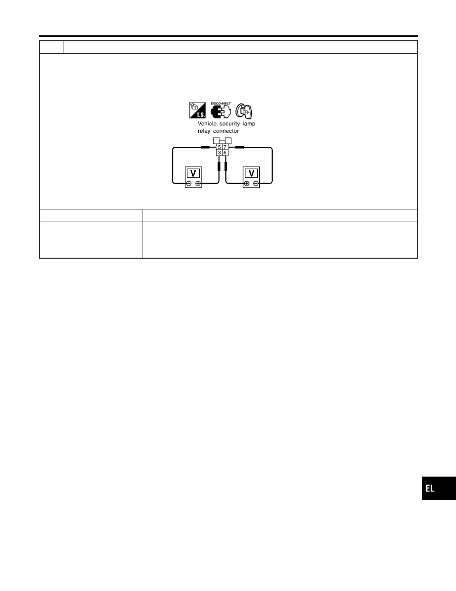
CHECK VEHICLE SECURITY LAMP RELAY CIRCUIT

1. Disconnect vehicle security lamp relay connector.
2. Check voltage between vehicle security lamp relay connector E48 terminals 3 (R) and 5 (R/G).

Battery voltage should exist.

3. Check voltage between vehicle security lamp relay connector E48 terminals 6 (R/W) and 7 (R/B).

Battery voltage should exist.

SEL957X

OK or NG

OK

©

Check harness for open or short between vehicle security lamp relay and control unit.

NG

©

Check the following.

I

15A fuse (No. 32 and 33, located in the fuse and fusible link box)

I

Harness for open or short between fuse and vehicle security lamp relay

I

Harness for open or short between vehicle security lamp relay and headlamps

GI

MA

EM

LC

EC

FE

CL

MT

AT

AX

SU

BR

ST

RS

BT

HA

SC

IDX

VEHICLE SECURITY (THEFT WARNING) SYSTEM

Trouble Diagnoses (Cont’d)

EL-241

Description

NCEL0124

The following systems are controlled by the smart entrance control unit.

I

Warning chime

I

Rear window defogger timer and door mirror defogger timer

I

Power door lock

I

Multi-remote control system

I

Vehicle security system

I

Interior room lamp timer

I

Electric sunroof and power window timer

I

Battery saver

For detailed description and wiring diagrams, refer to the relevant pages for the each system.
The smart entrance control unit receives data from the switches and sensors to control their corresponding
system relays and actuators.

INPUT/OUTPUT

NCEL0124S01

System

Input

Output

Power door lock

Door lock and unlock switch
Key switch (Insert)
Front door switch LH
Front door switch RH
Front door unlock sensor LH
Front door unlock sensor RH
Door key cylinder switches

Door lock actuator

Multi-remote control

Key switch (Insert)
Ignition switch (ACC)
Door switches
Door lock and unlock switch
Door unlock sensor (driver side)
Antenna (remote controller signal)

Horn relay
Vehicle security lamp relay
Interior room lamp
Multi-remote control relay
Door lock actuator
Trunk lid opener relay

Warning chime

Key switch (Insert)
Ignition switch (ON)
Lighting switch (1st)
Seat belt switch
Front door switch LH

Warning chime

Rear window defogger timer
and door mirror defogger timer

Ignition switch (ON)
Rear window defogger switch

Rear window defogger relay

Vehicle security

Ignition switch (ACC, ON)
Door switches
Hood switch
Trunk room lamp switch
Door key cylinder switches (lock/unlock)
Trunk lid key cylinder switch (unlock)
Door unlock sensors

Horn relay
Vehicle security lamp relay
Security indicator

Interior room lamp timer

Door switches
Door lock and unlock switch
Ignition switch (ON)
Key switch (Insert)

Interior room lamp

Electric sunroof and power
window timer

Ignition switch (ON)
Front door switches

Power window relay

Headlamp battery saver timer

Ignition switch (ON)
Front door switches

Headlamp battery saver control unit

Battery saver

Key switch (Insert)
Door switches
Door lock and unlock switch

Interior room lamp
Map lamp

SMART ENTRANCE CONTROL UNIT

Description

EL-242

BATTERY SAVER

NCEL0124S02

The lamp turns off automatically when the interior room lamp or/and map lamp is illuminated with the ignition
key in the OFF position, if the lamp remains lit by the door switch open signal or if the lamp switch is in the
ON position for more than 10 minutes.
After the battery saver system turns off the lamps, the lamps illuminate again when:

I

driver’s door is locked or unlocked,

I

door is opened or closed,

I

key is inserted in ignition key cylinder.

GI

MA

EM

LC

EC

FE

CL

MT

AT

AX

SU

BR

ST

RS

BT

HA

SC

IDX

SMART ENTRANCE CONTROL UNIT

Description (Cont’d)

EL-243

Schematic

NCEL0125

TEL778B

SMART ENTRANCE CONTROL UNIT

Schematic

EL-244


Content   ..  364  365  366  367   ..