Infiniti G20 (P11). Manual - part 347
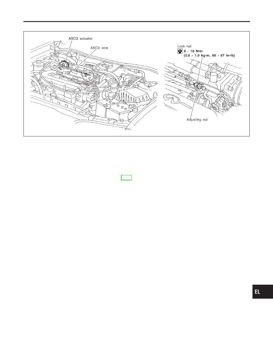
ASCD Wire Adjustment
=NCEL0101
CEL948
CAUTION:
I
Be careful not to twist ASCD wire when removing it.
I
Do not tense ASCD wire excessively during adjustment.
Adjust the tension of ASCD wire in the following manner.
1.
Loosen lock nut and adjusting nut.
2.
Make sure that accelerator wire is properly adjusted. Refer to
FE-3, “ACCELERATOR CONTROL SYSTEM”.
3.
Tighten adjusting nut just until throttle drum starts to move.
4.
Loosen adjusting nut again 1/2 to 1 turn.
5.
Tighten lock nut.
GI
MA
EM
LC
EC
FE
CL
MT
AT
AX
SU
BR
ST
RS
BT
HA
SC
IDX
AUTOMATIC SPEED CONTROL DEVICE (ASCD)
ASCD Wire Adjustment
EL-165