Infiniti G20 (P11). Manual - part 323
TEL690B
GI
MA
EM
LC
EC
FE
CL
MT
AT
AX
SU
BR
ST
RS
BT
HA
SC
IDX
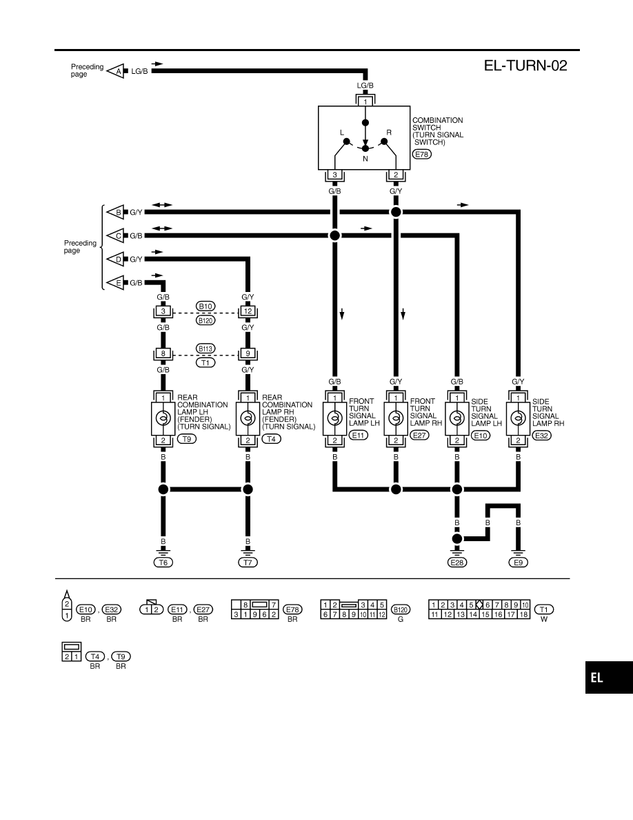
TURN SIGNAL AND HAZARD WARNING LAMPS
Wiring Diagram — TURN — (Cont’d)
EL-69
|
|
|
TEL690B GI MA EM LC EC FE CL MT AT AX SU BR ST RS BT HA SC IDX TURN SIGNAL AND HAZARD WARNING LAMPS Wiring Diagram — TURN — (Cont’d) EL-69 |